Friday , February 28 2025

how to configure trunk between Huawei router and switch

What we want to do is to configure 802.1q trunk between labnario1 router and labnarioSW1 switch, so that hosts from VLAN 100 will be able to ping the router’s interface.

Let’s look at the simple topology:

First we want to configure labnario1 router. To configure Ge0/0/1 interface to operate as a 802.1q trunk, we need to configure it as follows:

<labnario1>system-view
[labnario1]
[labnario1]interface GigabitEthernet 0/0/1
[labnario1-GigabitEthernet0/0/1]portswitch
[labnario1-GigabitEthernet0/0/1]port link-type trunk

Now we need to configure subinterface in VLAN 100 and define IP address. Of course our subinterface should be in the same VLAN as our hosts.

[labnario1]interface GigabitEthernet0/0/1.100
[labnario1-GigabitEthernet0/0/1.100]vlan-type dot1q 100
[labnario1-GigabitEthernet0/0/1.100]ip address 150.100.0.1 255.255.255.0

Labnario1 router configuration is finished. Now we can start configuring labnarioSW1 switch. Let’s start with 802.1q trunk configuration:

<labnario1>sys
[LabnarioSW1]
[LabnarioSW1]int GigabitEthernet 0/0/1
[LabnarioSW1-GigabitEthernet0/0/1]port link-type trunk
[LabnarioSW1-GigabitEthernet0/0/1]port trunk allow-pass vlan 100

Now we can add our hosts to VLAN 100:

[LabnarioSW1]interface Ethernet0/0/1
[LabnarioSW1-Ethernet0/0/1]port link-type access
[LabnarioSW1-Ethernet0/0/1] port default vlan 100
[LabnarioSW1]interface Ethernet0/0/2
[LabnarioSW1-Ethernet0/0/1]port link-type access
[LabnarioSW1-Ethernet0/0/1] port default vlan 100

As a last part of this configuration we need to add VLANIF interface on labnarioSW1:

[LabnarioSW1-Ethernet0/0/1]int vlanif100
[LabnarioSW1-Vlanif100]ip add 150.100.0.2 255.255.255.0

Both devices are configured. Let’s check if our hosts are able to ping router’s interface:

PC1>ping 150.100.0.2

Ping 150.100.0.2: 32 data bytes, Press Ctrl_C to break
From 150.100.0.2: bytes=32 seq=1 ttl=255 time=16 ms
From 150.100.0.2: bytes=32 seq=2 ttl=255 time=15 ms
From 150.100.0.2: bytes=32 seq=3 ttl=255 time=16 ms
From 150.100.0.2: bytes=32 seq=4 ttl=255 time=16 ms
From 150.100.0.2: bytes=32 seq=5 ttl=255 time=15 ms

--- 150.100.0.2 ping statistics ---
  5 packet(s) transmitted
  5 packet(s) received
  0.00% packet loss
  round-trip min/avg/max = 0/12/16 ms

PC2>ping 150.100.0.1

Ping 150.100.0.1: 32 data bytes, Press Ctrl_C to break
From 150.100.0.1: bytes=32 seq=1 ttl=255 time=16 ms
From 150.100.0.1: bytes=32 seq=2 ttl=255 time=78 ms
From 150.100.0.1: bytes=32 seq=3 ttl=255 time=47 ms
From 150.100.0.1: bytes=32 seq=4 ttl=255 time=16 ms
From 150.100.0.1: bytes=32 seq=5 ttl=255 time=47 ms

--- 150.100.0.1 ping statistics ---
  5 packet(s) transmitted
  5 packet(s) received
  0.00% packet loss
  round-trip min/avg/max = 16/40/78 ms

Read More »

link aggregation (IEEE802.3ad) on Huawei S5700

Link aggregation, in other words trunking, is a technique that helps to increase bandwidth by bundling multiple physical interfaces into a logical one, named Eth-trunk. Besides bandwidth increase, trunking lets us to implement load-balancing and ensure higher reliability.

Few restrictions must be taken into consideration when creating Eth-trunk interface:

  • parameters of physical interfaces (number, transmission rate, duplex mode and traffic-control mode) on both ends of the trunk link must be consistent.
  • data sequence must be unchanged (frames belonging to the same data flow are transmitted over the same physical link).

Eth-Trunk interfaces configured on S5700 switch support the following features:

  • Layer 2 forwarding and Layer 3 forwarding (unicast and multicast).
  • Hash algorithm-based load balancing.
  • QoS on the trunk interface.

There are 2 methods of link aggregation:

  • manual load balancing mode

Usually used if one of the devices, connected by Eth-trunk, does not support LACP. All active members interfaces forward data and perform load balancing. If an active link of the link aggregation group fails, traffic is balanced among the remaining active links. LACP is disabled.

  • static LACP mode.

LACP is enabled. When physical interfaces are added to an Eth-Trunk interface, devices at both ends negotiate aggregation parameters and determine active and inactive interfaces by sending LACPDUs to each other. Inactive interfaces are used for redundancy backup. When an active link fails, the backup link with the highest priority replaces the failed link and changes its status to active. The device in the link aggregation group with a higher LACP priority is the Actor, and the device with a lower LACP priority is the Partner. In case when they have the same LACP priority, the device with smaller MAC address becomes the Actor.

The process of setting up an Eth-Trunk link in static LACP mode:

  • LACP PDUs are sent between devices at both ends
  • Based on LACP system priority the Actor is determined.
  • Active interfaces are determined based on Actor’s LACP priority and interface ID (load-balancing is implemented across these active links).

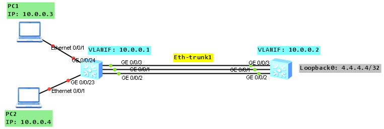
Let’s look at the topology:

As a configuration of manual load balancing mode is simple, we will focus on static LACP mode.

Based on the topology configure all necessary IP addresses:

labnario_1

#
interface Vlanif100
 ip address 10.0.0.1 255.255.255.0
#
interface GigabitEthernet0/0/23
 port link-type access
 port default vlan 100
#
interface GigabitEthernet0/0/24
 port link-type access
 port default vlan 100

labnario_2

#
interface Vlanif100
 ip address 10.0.0.2 255.255.255.0
#
interface LoopBack0
 ip address 4.4.4.4 255.255.255.255

Create Eth-trunk interface on both switches (labnario_1 as an example):

[labnario_1]interface Eth-Trunk 1
[labnario_1-Eth-Trunk1]bpdu enable 
[labnario_1-Eth-Trunk1]mode lacp-static

Add member interfaces to the Eth-trunk on both switches:

[labnario_1-Eth-Trunk1]trunkport GigabitEthernet 0/0/1 to 0/0/3 
Info: This operation may take a few seconds. Please wait for a moment....done.

You can add members to Eth-trunk in interface view as well.

Set the system priority on labnario_1 to 10 so that it becomes the Actor and set maximum of active interfaces to 2:

[labnario_1]lacp priority 10
[labnario_1]interface Eth-Trunk 1
[labnario_1-Eth-Trunk1]max active-linknumber 2

Verify the configuration on both switches:

[labnario_1]dis eth-trunk 1
Eth-Trunk1's state information is:
Local:
LAG ID: 1                   WorkingMode: STATIC                               
Preempt Delay: Disabled     Hash arithmetic: According to SIP-XOR-DIP         
System Priority: 10         System ID: 4c1f-cce4-15b4                         
Least Active-linknumber: 1  Max Active-linknumber: 2                          
Operate status: up          Number Of Up Port In Trunk: 2                     
--------------------------------------------------------------------------------

ActorPortName          Status   PortType PortPri PortNo PortKey PortState Weight

GigabitEthernet0/0/1   Selected 1000TG   32768   2      401     10111100  1     

GigabitEthernet0/0/2   Selected 1000TG   32768   3      401     10111100  1     

GigabitEthernet0/0/3   Unselect 1000TG   32768   4      401     10100000  1     

Partner:
--------------------------------------------------------------------------------

ActorPortName          SysPri   SystemID        PortPri PortNo PortKey PortState

GigabitEthernet0/0/1   32768    4c1f-ccb8-cad1  32768   2      401     10111100

GigabitEthernet0/0/2   32768    4c1f-ccb8-cad1  32768   3      401     10111100

GigabitEthernet0/0/3   32768    4c1f-ccb8-cad1  32768   4      401     10110000

[labnario_1]display trunkmembership eth-trunk 1
Trunk ID: 1 
Used status: VALID 
TYPE: ethernet 
Working Mode : Static 
Number Of Ports in Trunk = 3
Number Of Up Ports in Trunk = 2
Operate status: up 

Interface GigabitEthernet0/0/1, valid, operate up, weight=1
Interface GigabitEthernet0/0/2, valid, operate up, weight=1
Interface GigabitEthernet0/0/3, valid, operate down, weight=1

[labnario_2]dis eth-trunk 1
Eth-Trunk1's state information is:
Local:
LAG ID: 1                   WorkingMode: STATIC                               
Preempt Delay: Disabled     Hash arithmetic: According to SIP-XOR-DIP         
System Priority: 32768      System ID: 4c1f-ccb8-cad1                         
Least Active-linknumber: 1  Max Active-linknumber: 8                          
Operate status: up          Number Of Up Port In Trunk: 2                     
--------------------------------------------------------------------------------

ActorPortName          Status   PortType PortPri PortNo PortKey PortState Weight

GigabitEthernet0/0/1   Selected 1000TG   32768   2      401     10111100  1     

GigabitEthernet0/0/2   Selected 1000TG   32768   3      401     10111100  1     

GigabitEthernet0/0/3   Unselect 1000TG   32768   4      401     10110000  1     

Partner:
--------------------------------------------------------------------------------

ActorPortName          SysPri   SystemID        PortPri PortNo PortKey PortState

GigabitEthernet0/0/1   10       4c1f-cce4-15b4  32768   2      401     10111100

GigabitEthernet0/0/2   10       4c1f-cce4-15b4  32768   3      401     10111100

GigabitEthernet0/0/3   10       4c1f-cce4-15b4  32768   4      401     10100000

As you can see 2 ports are selected, valid and in UP state, LACP priority is 10, default port priority is 32768, default hash arithmetic is SIP-XOR-DIP (source and destination IP, it can be different on different switches).

Try to change GE0/0/1 and GE0/0/3 ports to be selected and make GE0/0/2 unselected, by configuring LACP priority on the interfaces. A smaller priority value indicates a higher LACP priority. Remember to enable LACP preemption function on Eth-trunk. The LACP preemption function ensures that the interface with the highest LACP priority always functions as an active interface, even if it comes back to UP state after a failure.

[labnario_1]int gig 0/0/1
[labnario_1-GigabitEthernet0/0/1]lacp priority 100
[labnario_1-GigabitEthernet0/0/1]int gig 0/0/3
[labnario_1-GigabitEthernet0/0/3]lacp priority 100

[labnario_1]int Eth-Trunk 1
[labnario_1-Eth-Trunk1]lacp preempt enable 
[labnario_1-Eth-Trunk1]lacp preempt delay 10

Let’s check what’s happened:

[labnario_1]dis eth-trunk 1
Eth-Trunk1's state information is:
Local:
LAG ID: 1                   WorkingMode: STATIC                               
Preempt Delay Time: 10      Hash arithmetic: According to SIP-XOR-DIP         
System Priority: 10         System ID: 4c1f-cce4-15b4                         
Least Active-linknumber: 1  Max Active-linknumber: 2                          
Operate status: up          Number Of Up Port In Trunk: 2                     
--------------------------------------------------------------------------------

ActorPortName          Status   PortType PortPri PortNo PortKey PortState Weight

GigabitEthernet0/0/1   Selected 1000TG   100     2      401     10111100  1     

GigabitEthernet0/0/2   Unselect 1000TG   32768   3      401     10100000  1     

GigabitEthernet0/0/3   Selected 1000TG   100     4      401     10111100  1     

Partner:
--------------------------------------------------------------------------------

ActorPortName          SysPri   SystemID        PortPri PortNo PortKey PortState

GigabitEthernet0/0/1   32768    4c1f-ccb8-cad1  32768   2      401     10111100

GigabitEthernet0/0/2   32768    4c1f-ccb8-cad1  32768   3      401     10110000

GigabitEthernet0/0/3   32768    4c1f-ccb8-cad1  32768   4      401     10111100

By default, the LACP preemption delay is 30 seconds.

Now we can check how hashing algorithm works. To do this we have to configure:

  • Eth-trunk port link-type as trunk and allow VLAN 100 to be passed through the trunk.
  • Static routing on labnario_1 to be able to ping loopback interface of labnario_2 and default routing on labnario_2 as well.
[labnario_1-Eth-Trunk1]port link-type trunk
[labnario_1-Eth-Trunk1]port trunk allow-pass vlan 100

[labnario_1]ip route-static 4.4.4.4 32 10.0.0.2

[labnario_2]ip route-static 0.0.0.0 0 10.0.0.1

[labnario_1]ping 4.4.4.4
  PING 4.4.4.4: 56  data bytes, press CTRL_C to break
    Reply from 4.4.4.4: bytes=56 Sequence=1 ttl=255 time=580 ms
    Reply from 4.4.4.4: bytes=56 Sequence=2 ttl=255 time=60 ms
    Reply from 4.4.4.4: bytes=56 Sequence=3 ttl=255 time=30 ms
    Reply from 4.4.4.4: bytes=56 Sequence=4 ttl=255 time=30 ms
    Reply from 4.4.4.4: bytes=56 Sequence=5 ttl=255 time=40 ms

  --- 4.4.4.4 ping statistics ---
    5 packet(s) transmitted
    5 packet(s) received
    0.00% packet loss
    round-trip min/avg/max = 30/148/580 ms

Now we can ping from PC1 to 4.4.4.4 and check statistics of members of Eth-trunk interface:

PC>ping 4.4.4.4 -t

Ping 4.4.4.4: 32 data bytes, Press Ctrl_C to break
From 4.4.4.4: bytes=32 seq=1 ttl=255 time=31 ms
From 4.4.4.4: bytes=32 seq=2 ttl=255 time=47 ms
From 4.4.4.4: bytes=32 seq=3 ttl=255 time=47 ms
From 4.4.4.4: bytes=32 seq=4 ttl=255 time=31 ms
From 4.4.4.4: bytes=32 seq=5 ttl=255 time=31 ms
From 4.4.4.4: bytes=32 seq=6 ttl=255 time=31 ms
From 4.4.4.4: bytes=32 seq=7 ttl=255 time=47 ms
From 4.4.4.4: bytes=32 seq=8 ttl=255 time=31 ms
From 4.4.4.4: bytes=32 seq=9 ttl=255 time=15 ms
From 4.4.4.4: bytes=32 seq=10 ttl=255 time=31 ms
From 4.4.4.4: bytes=32 seq=11 ttl=255 time=31 ms
From 4.4.4.4: bytes=32 seq=12 ttl=255 time=31 ms
From 4.4.4.4: bytes=32 seq=13 ttl=255 time=47 ms
From 4.4.4.4: bytes=32 seq=14 ttl=255 time=47 ms
From 4.4.4.4: bytes=32 seq=15 ttl=255 time=63 ms
From 4.4.4.4: bytes=32 seq=16 ttl=255 time=47 ms
From 4.4.4.4: bytes=32 seq=17 ttl=255 time=46 ms
From 4.4.4.4: bytes=32 seq=18 ttl=255 time=47 ms
From 4.4.4.4: bytes=32 seq=19 ttl=255 time=32 ms
From 4.4.4.4: bytes=32 seq=20 ttl=255 time=31 ms
From 4.4.4.4: bytes=32 seq=21 ttl=255 time=32 ms
From 4.4.4.4: bytes=32 seq=22 ttl=255 time=31 ms
From 4.4.4.4: bytes=32 seq=23 ttl=255 time=31 ms
From 4.4.4.4: bytes=32 seq=24 ttl=255 time=47 ms
From 4.4.4.4: bytes=32 seq=25 ttl=255 time=47 ms

--- 4.4.4.4 ping statistics ---
  26 packet(s) transmitted
  26 packet(s) received
  0% packet loss
  round-trip min/avg/max = 15/38/63 ms

<labnario_1>dis int gig 0/0/1 | inc Unicast
      Unicast: 26 packets, Multicast: 45 packets
      Unicast: 26 packets, Multicast: 3 packets

<labnario_1>dis int gig 0/0/2 | inc Unicast
      Unicast: 0 packets, Multicast: 19 packets
      Unicast: 0 packets, Multicast: 19 packets

<labnario_1>dis int gig 0/0/3 | inc Unicast
      Unicast: 0 packets, Multicast: 18 packets
      Unicast: 0 packets, Multicast: 19 packets

As you can see all traffic is going by interface GE0/0/1. This is per-flow behaviour. It means that frames belonging to the same data flow are transmitted over the same physical link.

And catched packets on GE0/0/1:
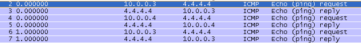
Read More »

Link Layer Discovery Protocol (LLDP) on Huawei S3300

The Link Layer Discovery Protocol (LLDP) is an layer 2 discovery protocol defined in the IEEE 802.1ab. How does it work? The LLDP protocol collects information about local interfaces, sends this information to neighbours, and receives information from the neighbours as well. In short, when the LLDP protocol runs on devices, the NMS can obtain the Layer 2 information about all the devices it connects and the detailed network topology. It does it by searching the layer 2 information in Management Information Base (MIB). NMS uses LLDP management address to identify the device. Trap message is triggered in case when local management address is changed, LLDP is enabled or disabled globally and there are changes on neighbouring devices.

Lets try to configure LLDP based on the following topology:

First of all configure SNMP trap for LLDP:

[Switch]snmp-agent trap enable feature-name lldptrap

[Quidway]dis snmp-agent tr feature-name lldptrap all
------------------------------------------------------------------------------
Feature name: LLDPTRAP                      
Trap number : 4         
------------------------------------------------------------------------------
Trap name                       Default switch status   Current switch status 
lldpRemTablesChange             on                      on                  
hwLldpEnabled                   on                      on                  
hwLldpDisabled                  on                      on                  
hwLldpLocManIPAddrChange        on                      on

And now turn on traps to be displayed on the screen:

<Switch>terminal monitor 
Info: Current terminal monitor is on.
<Switch>terminal trapping 
Info: Current Terminal trapping is on.

Enable LLDP globally and look what kind of trap will be displayed:

[Switch]lldp enable
Info: Global LLDP is enabled successfully.

Nov 27 2012 16:16:37 Quidway LLDP/4/ENABLETRAP:OID: 1.3.6.1.4.1.2011.5.25.134.2.1 Global LLDP is enabled.

Configure LLDP management address:

[Switch]lldp management-address 10.0.0.1

Info: Setting management address successfully.
Nov 27 2012 16:18:30 Quidway LLDP/4/ADDCHGTRAP:OID: 1.3.6.1.4.1.2011.5.25.134.2.5 Local management address is changed. (LocManIPAddr=10.0.0.1)

[Switch]dis lldp local 
System information
Chassis type   :macAddress 
Chassis ID     :286e-d49b-8c72
System name    :Switch
System description  :S3328TP-SI 
Huawei Versatile Routing Platform Software 
 VRP (R) software,Version 5.70 (S3328 V100R005C00SPC100) 
 Copyright (C) 2003-2010 Huawei Technologies Co., Ltd.
System capabilities supported   :bridge  
System capabilities enabled     :bridge  
LLDP Up time   :2012/11/27 16:16:37

MED system information
Device class   :Network Connectivity
(MED inventory information of master board)
HardwareRev       :VER B

FirmwareRev       :NA
SoftwareRev       :Version 5.70 V100R005C00SPC100
SerialNum         :NA
Manufacturer name :HUAWEI TECH CO., LTD
Model name        :NA
Asset tracking identifier :NA                     
System configuration
LLDP Status                     :enabled             (default is disabled)
LLDP Message Tx Interval        :30                  (default is 30s)     
LLDP Message Tx Hold Multiplier :4                   (default is 4)       
LLDP Refresh Delay              :2                   (default is 2s)      
LLDP Tx Delay                   :2                   (default is 2s)      
LLDP Notification Interval      :5                   (default is 5s)      
LLDP Notification Enable        :enabled             (default is disabled)
Management Address              :IP: 10.0.0.1  

Remote Table Statistics:
Remote Table Last Change Time   :0 days, 0 hours, 50 minutes, 36 seconds         
Remote Neighbors Added          :1                                               
Remote Neighbors Deleted        :0                                               
Remote Neighbors Dropped        :0                                               
Remote Neighbors Aged           :0                                               
Total Neighbors                 :1                                               

Port information:

Interface Ethernet0/0/1:
LLDP Enable Status       :enabled             (default is disabled)
Total Neighbors          :1

Port ID subtype     :interfaceName 
Port ID             :Ethernet0/0/1 
Port description    :test

Port And Protocol VLAN ID(PPVID) don't supported
Port VLAN ID(PVID)  :1
VLAN name of VLAN 1: VLAN1
Protocol identity   :STP RSTP/MSTP LACP EthOAM CFM 

Auto-negotiation supported    :Yes 
Auto-negotiation enabled      :Yes
OperMau   :speed(100)/duplex(Half)

Power port class         :'PD 
PSE power supported      :No 
PSE power enabled        :No 
PSE pairs control ability:No 
Power pairs              :Unknown 
Port power classification:Unknown

Link aggregation supported:Yes 
Link aggregation enabled :No 
Aggregation port ID      :0 
Maximum frame Size       :1600

MED port information

Media policy type   :Unknown 
Unknown Policy      :Yes 
VLAN tagged         :No 
Media policy VlanID           :0 
Media policy L2 priority      :0 
Media policy Dscp             :0

Power Type               :Unknown 
PoE PSE power source     :Unknown 
Port PSE Priority        :Unknown 
Port Available power value:0
...

[Switch]dis lldp neighbor 

Ethernet0/0/1 has 1 neighbors:

Neighbor index : 1
Chassis type   :macAddress 
Chassis ID     :286e-d49b-8c17 
Port ID type   :interfaceName 
Port ID        :Ethernet0/0/1
Port description    :test
System name         :labnario
System description  :S3328TP-SI 
Huawei Versatile Routing Platform Software 
 VRP (R) software,Version 5.70 (S3328 V100R005C00SPC100) 
 Copyright (C) 2003-2010 Huawei Technologies Co., Ltd.
System capabilities supported   :bridge 
System capabilities enabled     :bridge 
Management address type  :ipV4
Management address       : 172.16.1.1  
Expired time   :117s

Port VLAN ID(PVID)  :1
VLAN name of VLAN  1: VLAN1
Protocol identity   :STP RSTP/MSTP LACP EthOAM CFM 

Auto-negotiation supported    :Yes 
Auto-negotiation enabled      :No
OperMau   :speed(100)/duplex(Full)

Power port class         :'PD 
PSE power supported      :No 
PSE power enabled        :No 
PSE pairs control ability:No 
Power pairs              :Unknown 
Port power classification:Unknown

Link aggregation supported:Yes 
Link aggregation enabled :No 
Aggregation port ID      :0 
Maximum frame Size       :1600

MED Device information             
Device class   :Network Connectivity

HardwareRev       :VER B

FirmwareRev       :NA
SoftwareRev       :Version 5.70 V100R005C00SPC100
SerialNum         :NA
Manufacturer name :HUAWEI TECH CO., LTD
Model name        :NA
Asset tracking identifier :NA

Media policy type   :Voice 
Unknown Policy      :'Defined 
VLAN tagged         :Yes 
Media policy VlanID      :0 
Media policy L2 priority :6 
Media policy Dscp        :46

Power Type               :Unknown 
PoE PSE power source     :Unknown 
Port PSE Priority        :Unknown 
Port Available power value:2
Ethernet0/0/2 has 0 neighbors

Ethernet0/0/3 has 0 neighbors

Ethernet0/0/4 has 0 neighbors

Ethernet0/0/5 has 0 neighbors

Ethernet0/0/6 has 0 neighbors

Ethernet0/0/7 has 0 neighbors

Ethernet0/0/8 has 0 neighbors

Ethernet0/0/9 has 0 neighbors

Ethernet0/0/10 has 0 neighbors

Ethernet0/0/11 has 0 neighbors

Ethernet0/0/12 has 0 neighbors

Ethernet0/0/13 has 0 neighbors

Ethernet0/0/14 has 0 neighbors

Ethernet0/0/15 has 0 neighbors

Ethernet0/0/16 has 0 neighbors

Ethernet0/0/17 has 0 neighbors

Ethernet0/0/18 has 0 neighbors

Ethernet0/0/19 has 0 neighbors

Ethernet0/0/20 has 0 neighbors

Ethernet0/0/21 has 0 neighbors

Ethernet0/0/22 has 0 neighbors

Ethernet0/0/23 has 0 neighbors

Ethernet0/0/24 has 0 neighbors

GigabitEthernet0/0/1 has 0 neighbors

GigabitEthernet0/0/2 has 0 neighbors

GigabitEthernet0/0/3 has 0 neighbors

GigabitEthernet0/0/4 has 0 neighbors

Now change physical parameters of neighbouring interfaces and trap will be send to NMS that LLDP neighbour information is changed:

Nov 27 2012 16:19:26 Quidway SNMP/2/IF_PVCDOWN:OID 1.3.6.1.6.3.1.1.5.3 Interface 4 turned into DOWN state.
Nov 27 2012 16:19:26 Quidway SNMP/2/IF_PVCDOWN:OID 1.3.6.1.6.3.1.1.5.3 Interface 32 turned into DOWN state.
Nov 27 2012 16:19:26 Quidway LLDP/4/NBRCHGTRAP:OID: 1.0.8802.1.1.2.0.0.1 Neighbor information is changed. (LldpStatsRemTablesInserts=0, LldpStatsRemTablesDeletes=1, LldpStatsRemTablesDrops=0, LldpStatsRemTablesAgeouts=0)
Nov 27 2012 16:19:26 Quidway %%01IFNET/4/IF_STATE(l)[6]:Interface Ethernet0/0/1 has turned into DOWN state.
Nov 27 2012 16:19:26 Quidway %%01IFNET/4/IF_STATE(l)[7]:Interface Vlanif1 has turned into DOWN state.
Nov 27 2012 16:19:26 Quidway %%01IFNET/4/LINKNO_STATE(l)[8]:The line protocol on the interface Vlanif1 has entered the DOWN state.
Nov 27 2012 16:19:30 Quidway SNMP/2/IF_PVCUP:OID 1.3.6.1.6.3.1.1.5.4 Interface 4 turned into UP state.
Nov 27 2012 16:19:30 Quidway SNMP/2/IF_PVCUP:OID 1.3.6.1.6.3.1.1.5.4 Interface 32 turned into UP state.
Nov 27 2012 16:19:30 Quidway SRM/4/PortPhysicalEthHalfDuplexClear:OID 1.3.6.1.4.1.2011.5.25.129.2.5.12 port work at full-duplex state.(EntityPhysicalIndex=4, BaseTrapSeverity=4, BaseTrapProbableCause=1024, BaseTrapEventType=0, EntPhysicalName=Ethernet0/0/1, RelativeResource=interface Ethernet0/0/1)
Nov 27 2012 16:19:30 Quidway %%01IFNET/4/IF_STATE(l)[9]:Interface Ethernet0/0/1 has turned into UP state.
Nov 27 2012 16:19:30 Quidway %%01IFNET/4/IF_STATE(l)[10]:Interface Vlanif1 has turned into UP state.
Nov 27 2012 16:19:30 Quidway %%01IFNET/4/LINKNO_STATE(l)[11]:The line protocol on the interface Vlanif1 has entered the UP state.

We can also display LLDP statistics:

[Switch]dis lldp stat
LLDP statistics global Information:
Statistics for Ethernet0/0/1: 
Transmitted Frames Total: 23        
Received Frames Total:    19        Frames Discarded Total:  0         
Frames Error Total:       0         TLVs Discarded Total:    0         
TLVs Unrecognized Total:  0         Neighbors Expired Total: 0

You can also turn on LLDP debugging to follow if LLDP information is exchanged:

<Quidway>debugging lldp all
<Quidway>terminal monitor
Info: Current terminal monitor is on.
<Quidway>terminal debugging
Info: Current terminal debugging is on.

Nov 27 2012 16:24:25.420.1 Quidway LLDP/7/LLDP Debug:LLDP DEBUG INFO:
[LLDP-Evt] [LLDP_SH_CaptureEthPkt] Port 0x00000004 receive a pkt 
 (usTPID: 0x8100, usLenEtype: 0x88cc)

Nov 27 2012 16:24:25.420.2 Quidway LLDP/7/LLDP Debug:LLDP DEBUG INFO:
[LLDP-Evt] [LLDP_SH_CaptureEthPkt] get vlan(1) cut. 

Nov 27 2012 16:24:25.420.3 Quidway LLDP/7/LLDP Debug:LLDP DEBUG INFO:
[LLDP-Evt] [LLDP_SH_CaptureEthPkt] port 0x00000004 ready to handle lldp pkt. 

Nov 27 2012 16:24:25.420.4 Quidway LLDP/7/LLDP Debug:LLDP DEBUG INFO:
[LLDP-Evt]  The port(0x00000004) receive a lldp packet. 

Nov 27 2012 16:24:25.420.5 Quidway LLDP/7/LLDP Debug:LLDP DEBUG INFO: 01 80 C2 00 00 0E 28 6E D4 9B 8C 17 88 CC 02 07 04 28 6E D4 9B 8C 17 04 0E 05 45 74 68 65 72 6E 65 74 30 2F 30 2F 31 06 02 00 78 08 04 74 65 73 74 0A 08 6C 61 62 6E 61 72 69 6F 0C AB 53 33 33 32 38 54 50 2D 53 49 20 0D 0A 48 75 61 77 65 69 20 56 65 72 73 61 74 69 6C 65 20 52 6F 75 74 69 6E 67 20 50 6C 61 74 66 6F 72 6D 20 53 6F 66 74 77 61 72 65 20 0D 0A 20 56 52 50 20 28 52 29 20
Nov 27 2012 16:24:25.420.6 Quidway LLDP/7/LLDP Debug:LLDP DEBUG INFO: 73 6F 66 74 77 61 72 65 2C 56 65 72 73 69 6F 6E 20 35 2E 37 30 20 28 53 33 33 32 38 20 56 31 30 30 52 30 30 35 43 30 30 53 50 43 31 30 30 29 20 0D 0A 20 43 6F 70 79 72 69 67 68 74 20 28 43 29 20 32 30 30 33 2D 32 30 31 30 20 48 75 61 77 65 69 20 54 65 63 68 6E 6F 6C 6F 67 69 65 73 20 43 6F 2E 2C 20 4C 74 64 2E 0E 04 00 04 00 04 10 1D 05 01 AC 10 01 01 02 00 00 00 22 11 06 0F 2B 06
Nov 27 2012 16:24:25.420.7 Quidway LLDP/7/LLDP Debug:LLDP DEBUG INFO: 01 04 01 8F 5B 05 19 29 01 02 01 01 01 FE 06 00 80 C2 01 00 01 FE 07 00 80 C2 02 00 00 00 FE 0C 00 80 C2 03 00 01 05 56 4C 41 4E 31 FE 10 00 80 C2 04 0B 31 35 30 30 34 32 34 32 33 30 30 FE 10 00 80 C2 04 0B 31 35 30 30 34 32 34 32 33 32 30 FE 0B 00 80 C2 04 06 38 38 30 39 31 31 FE 0A 00 80 C2 04 05 38 38 30 39 33 FE 09 00 80 C2 04 04 38 39 30 32 FE 09 00 12 0F 01 03 A0 3E 00 10 FE
Nov 27 2012 16:24:25.420.8 Quidway LLDP/7/LLDP Debug:LLDP DEBUG INFO: 07 00 12 0F 02 00 00 00 FE 09 00 12 0F 03 01 00 00 00 00 FE 06 00 12 0F 04 06 40 FE 07 00 12 BB 01 00 3B 04 FE 08 00 12 BB 02 01 40 01 AE FE 07 00 12 BB 04 80 00 02 FE 0B 00 12 BB 05 56 45 52 20 42 0D 0A FE 05 00 12 BB 06 00 FE 22 00 12 BB 07 56 65 72 73 69 6F 6E 20 35 2E 37 30 20 56 31 30 30 52 30 30 35 43 30 30 53 50 43 31 30 30 FE 05 00 12 BB 08 00 FE 18 00 12 BB 09 48 55 41 57
Nov 27 2012 16:24:25.420.9 Quidway LLDP/7/LLDP Debug:LLDP DEBUG INFO: 45 49 20 54 45 43 48 20 43 4F 2E 2C 20 4C 54 44 FE 05 00 12 BB 0A 00 FE 05 00 12 BB 0B 00 00 00
Nov 27 2012 16:24:25.420.10 Quidway LLDP/7/LLDP Debug:LLDP DEBUG INFO:
[LLDP-Evt] This neighour is exist. ifindex[4]

If you want to test it on eNSP, unfortunately I was not able to do it. It looks like LLDP is not supported yet, even the necessary commands are available.

Read More »

VLAN, trunk, VLANIF (SVI) on Huawei switch

Today I want to show you:

  • How to configure VLANs
  • How to add interface to a VLAN
  • How to establish 802.1q trunk between two Ethernet switches and filter VLANs
  • How to configure VLANIF (VLAN interface or simply SVI).

Look at the following topology:

Let’s assume that we want to configure two switches, which are connected via Ethernet link. Both switches have PCs connected to them. We want to allow PC101 to be able to reach PC102 and PC201 to be able to reach PC202.To do so, we need to add two different VLANs, configure Ethernet Trunk between switches and add PCs to the correct VLAN.

Let’s start with SW1 switch configuration.

First I have to add two VLANs 100 and 200, and describe these VLANs labnario100 and labnario200 respectively (description is optional). Both switches should be configured at exactly the same way, so SW2 configuration is omitted.

<labnariosw1>system-view
[labnariosw1]vlan 100	
[labnariosw1-vlan100]description labnario100
[labnariosw1-vlan100]vlan 200
[labnariosw1-vlan200]description labnario200

Let’s verify VLAN configuration:

[labnariosw1]display vlan
The total number of vlans is : 3
--------------------------------------------------------------------------------

U: Up;         D: Down;         TG: Tagged;         UT: Untagged;
MP: Vlan-mapping;               ST: Vlan-stacking;
#: ProtocolTransparent-vlan;    *: Management-vlan;
--------------------------------------------------------------------------------

VID  Type    Ports                
--------------------------------------------------------------------------------
1    common  UT:GE0/0/1(U)      GE0/0/2(U)      GE0/0/3(D)      GE0/0/4(D)      
                GE0/0/5(D)      GE0/0/6(D)      GE0/0/7(D)      GE0/0/8(D)      
                GE0/0/9(D)      GE0/0/10(U)     GE0/0/11(D)     GE0/0/12(D)     
                GE0/0/13(D)     GE0/0/14(D)     GE0/0/15(D)     GE0/0/16(D)     
                GE0/0/17(D)     GE0/0/18(D)     GE0/0/19(D)     GE0/0/20(D)     
                GE0/0/21(D)     GE0/0/22(D)     GE0/0/23(D)     GE0/0/24(D)     
100  common  
200  common  

VID  Status  Property      MAC-LRN Statistics Description      
--------------------------------------------------------------------------------
1    enable  default       enable  disable    VLAN 0001                         
100  enable  default       enable  disable    labnario100                       
200  enable  default       enable  disable    labnario200

As the second step, I want to configure 802.1q trunk between SW1 and SW2 and filter VLANs, which can pass through this trunk (VLAN filtering is optional):

[labnariosw1-GigabitEthernet0/0/10]port link-type trunk
[labnariosw1-GigabitEthernet0/0/10]port trunk allow-pass vlan 100 200

Let’s verify, if our trunk interface is configured correctly:

[labnariosw1]display port vlan 
Port                    Link Type    PVID  Trunk VLAN List
-------------------------------------------------------------------------------
GigabitEthernet0/0/1    hybrid       1     -                                   
GigabitEthernet0/0/2    hybrid       1     -                                   
GigabitEthernet0/0/3    hybrid       1     -                                   
GigabitEthernet0/0/4    hybrid       1     -                                   
GigabitEthernet0/0/5    hybrid       1     -                                   
GigabitEthernet0/0/6    hybrid       1     -                                   
GigabitEthernet0/0/7    hybrid       1     -                                   
GigabitEthernet0/0/8    hybrid       1     -                                   
GigabitEthernet0/0/9    hybrid       1     -                                   
GigabitEthernet0/0/10   trunk        1     1 100 200
GigabitEthernet0/0/11   hybrid       1     -                                   
GigabitEthernet0/0/12   hybrid       1     -                                   
GigabitEthernet0/0/13   hybrid       1     -                                   
GigabitEthernet0/0/14   hybrid       1     -                                   
GigabitEthernet0/0/15   hybrid       1     -                                   
GigabitEthernet0/0/16   hybrid       1     -                                   
GigabitEthernet0/0/17   hybrid       1     -                                   
GigabitEthernet0/0/18   hybrid       1     -                                   
GigabitEthernet0/0/19   hybrid       1     -                                   
GigabitEthernet0/0/20   hybrid       1     -                                   
GigabitEthernet0/0/21   hybrid       1     -                                   
GigabitEthernet0/0/22   hybrid       1     -                                   
GigabitEthernet0/0/23   hybrid       1     -                                   
GigabitEthernet0/0/24   hybrid       1     -

There is also more specific command:

[labnariosw1]display port vlan GigabitEthernet 0/0/10
Port                    Link Type    PVID  Trunk VLAN List
-------------------------------------------------------------------------------
GigabitEthernet0/0/10   trunk        1     1 100 200

You can also filter VLANs which can pass through the trunk:

[labnariosw1-GigabitEthernet0/0/10]undo port trunk allow-pass vlan 1
[labnariosw1]display port vlan GigabitEthernet 0/0/10
Port                    Link Type    PVID  Trunk VLAN List
-------------------------------------------------------------------------------
GigabitEthernet0/0/10   trunk        1     100 200

As you see, Ge0/0/10 interface is working as a 802.1q trunk. Only VLANs 100 and 200 can pass through this trunk link.

Now we can configure access ports which are connected to PCs:

[labnariosw1]interface GigabitEthernet 0/0/1
[labnariosw1-GigabitEthernet0/0/1]port link-type access
[labnariosw1-GigabitEthernet0/0/1]port default vlan 100
[labnariosw1-GigabitEthernet0/0/1]interface GigabitEthernet 0/0/2
[labnariosw1-GigabitEthernet0/0/2]port link-type access
[labnariosw1-GigabitEthernet0/0/2]port default vlan 200

Let’s verify our VLANs and ports configuration again:

[labnariosw1]display port vlan
Port                    Link Type    PVID  Trunk VLAN List
-------------------------------------------------------------------------------
GigabitEthernet0/0/1    access       100   -                                   
GigabitEthernet0/0/2    access       200   -                                   
GigabitEthernet0/0/3    hybrid       1     -                                   
GigabitEthernet0/0/4    hybrid       1     -                                   
GigabitEthernet0/0/5    hybrid       1     -                                   
GigabitEthernet0/0/6    hybrid       1     -                                   
GigabitEthernet0/0/7    hybrid       1     -                                   
GigabitEthernet0/0/8    hybrid       1     -                                   
GigabitEthernet0/0/9    hybrid       1     -                                   
GigabitEthernet0/0/10   trunk        1     100 200
GigabitEthernet0/0/11   hybrid       1     -                                   
GigabitEthernet0/0/12   hybrid       1     -                                   
GigabitEthernet0/0/13   hybrid       1     -                                   
GigabitEthernet0/0/14   hybrid       1     -                                   
GigabitEthernet0/0/15   hybrid       1     -                                   
GigabitEthernet0/0/16   hybrid       1     -                                   
GigabitEthernet0/0/17   hybrid       1     -                                   
GigabitEthernet0/0/18   hybrid       1     -                                   
GigabitEthernet0/0/19   hybrid       1     -                                   
GigabitEthernet0/0/20   hybrid       1     -                                   
GigabitEthernet0/0/21   hybrid       1     -                                   
GigabitEthernet0/0/22   hybrid       1     -                                   
GigabitEthernet0/0/23   hybrid       1     -                                   
GigabitEthernet0/0/24   hybrid       1     -   

[labnariosw1]display vlan
The total number of vlans is : 3
--------------------------------------------------------------------------------

U: Up;         D: Down;         TG: Tagged;         UT: Untagged;
MP: Vlan-mapping;               ST: Vlan-stacking;
#: ProtocolTransparent-vlan;    *: Management-vlan;
--------------------------------------------------------------------------------

VID  Type    Ports                
--------------------------------------------------------------------------------
1    common  UT:GE0/0/3(D)      GE0/0/4(D)      GE0/0/5(D)      GE0/0/6(D)      
                GE0/0/7(D)      GE0/0/8(D)      GE0/0/9(D)      GE0/0/10(U)     
                GE0/0/11(D)     GE0/0/12(D)     GE0/0/13(D)     GE0/0/14(D)     
                GE0/0/15(D)     GE0/0/16(D)     GE0/0/17(D)     GE0/0/18(D)     
                GE0/0/19(D)     GE0/0/20(D)     GE0/0/21(D)     GE0/0/22(D)     
                GE0/0/23(D)     GE0/0/24(D)                                     
100  common  UT:GE0/0/1(U)            
             TG:GE0/0/10(U)           
200  common  UT:GE0/0/2(U)            
             TG:GE0/0/10(U)           

VID  Status  Property      MAC-LRN Statistics Description      
--------------------------------------------------------------------------------
1    enable  default       enable  disable    VLAN 0001                         
100  enable  default       enable  disable    labnario100                       
200  enable  default       enable  disable    labnario200

When both switches are configured, we can check if our PCs can ping each other. Remember that PC101 and PC102 are both in a VLAN 100 and PC201 with PC202 are both in a VLAN 200. So let’s start with PC101:

PC101>ping 192.168.100.2

Ping 192.168.100.2: 32 data bytes, Press Ctrl_C to break
From 192.168.100.2: bytes=32 seq=1 ttl=128 time=15 ms
From 192.168.100.2: bytes=32 seq=2 ttl=128 time=32 ms
From 192.168.100.2: bytes=32 seq=3 ttl=128 time=47 ms
From 192.168.100.2: bytes=32 seq=4 ttl=128 time=46 ms
From 192.168.100.2: bytes=32 seq=5 ttl=128 time=16 ms

--- 192.168.100.2 ping statistics ---
  5 packet(s) transmitted
  5 packet(s) received
  0.00% packet loss
  round-trip min/avg/max = 15/31/47 ms

PC101>ping 192.168.200.1

Ping 192.168.200.1: 32 data bytes, Press Ctrl_C to break
From 192.168.100.1: Destination host unreachable

PC101>ping 192.168.200.2

Ping 192.168.200.2: 32 data bytes, Press Ctrl_C to break
From 192.168.100.1: Destination host unreachable

PC101 can successfully ping PC102 as both are in a VLAN 100. It can not ping PCs 201 and 202 which are configured in VLAN 200. Let’s check connectivity in VLAN 200:

PC201>ping 192.168.200.2

Ping 192.168.200.2: 32 data bytes, Press Ctrl_C to break
From 192.168.200.2: bytes=32 seq=1 ttl=128 time=46 ms
From 192.168.200.2: bytes=32 seq=2 ttl=128 time=16 ms
From 192.168.200.2: bytes=32 seq=3 ttl=128 time=63 ms
From 192.168.200.2: bytes=32 seq=4 ttl=128 time=46 ms
From 192.168.200.2: bytes=32 seq=5 ttl=128 time=47 ms

--- 192.168.200.2 ping statistics ---
  5 packet(s) transmitted
  5 packet(s) received
  0.00% packet loss
  round-trip min/avg/max = 16/43/63 ms

PC201 can successfully ping PC202. It means that our VLANs, trunk and access ports are configured correctly.

As the last step I want to show you, how to configure VLAN interface.

VLAN interface is a Layer3 virtual interface configured on a switch, which belongs to a specific VLAN. It is sometimes called a “SVI” (Switched Virtual Interface). If there is no VLANIF configured, it is not possible to ping any device connected to that VLAN. This is because IP packets must have source IP address to be able to reach remote device and come back to our switch.

I will configure VLANIF 100 on both SW1 and SW2:

[labnariosw1]interface Vlanif 100
[labnariosw1-Vlanif100]ip add 192.168.100.101 255.255.255.0

[labnariosw2]interface Vlanif 100
[labnariosw2-Vlanif100]ip add 192.168.100.102 255.255.255.0

Now I should have full IP connectivity between all my devices configured in VLAN 100. This means that PC101, PC102, SW1 and SW2 can ping each other:

[labnariosw1]ping 192.168.100.1
  PING 192.168.100.1: 56  data bytes, press CTRL_C to break
    Reply from 192.168.100.1: bytes=56 Sequence=1 ttl=128 time=50 ms
    Reply from 192.168.100.1: bytes=56 Sequence=2 ttl=128 time=1 ms
    Reply from 192.168.100.1: bytes=56 Sequence=3 ttl=128 time=20 ms
    Reply from 192.168.100.1: bytes=56 Sequence=4 ttl=128 time=20 ms
    Reply from 192.168.100.1: bytes=56 Sequence=5 ttl=128 time=1 ms

  --- 192.168.100.1 ping statistics ---
    5 packet(s) transmitted
    5 packet(s) received
    0.00% packet loss
    round-trip min/avg/max = 1/18/50 ms

[labnariosw1]ping 192.168.100.2
  PING 192.168.100.2: 56  data bytes, press CTRL_C to break
    Reply from 192.168.100.2: bytes=56 Sequence=1 ttl=128 time=60 ms
    Reply from 192.168.100.2: bytes=56 Sequence=2 ttl=128 time=10 ms
    Reply from 192.168.100.2: bytes=56 Sequence=3 ttl=128 time=40 ms
    Reply from 192.168.100.2: bytes=56 Sequence=4 ttl=128 time=40 ms
    Reply from 192.168.100.2: bytes=56 Sequence=5 ttl=128 time=30 ms

  --- 192.168.100.2 ping statistics ---
    5 packet(s) transmitted
    5 packet(s) received
    0.00% packet loss
    round-trip min/avg/max = 10/36/60 ms

[labnariosw1]ping 192.168.100.102
  PING 192.168.100.102: 56  data bytes, press CTRL_C to break
    Reply from 192.168.100.102: bytes=56 Sequence=1 ttl=255 time=30 ms
    Reply from 192.168.100.102: bytes=56 Sequence=2 ttl=255 time=50 ms
    Reply from 192.168.100.102: bytes=56 Sequence=3 ttl=255 time=40 ms
    Reply from 192.168.100.102: bytes=56 Sequence=4 ttl=255 time=50 ms
    Reply from 192.168.100.102: bytes=56 Sequence=5 ttl=255 time=40 ms

  --- 192.168.100.102 ping statistics ---
    5 packet(s) transmitted
    5 packet(s) received
    0.00% packet loss
    round-trip min/avg/max = 30/42/50 ms

Read More »

how to display power of optical module

Let’s take Huawei’s S3328TP-SI switch as an example. This switch has 2 combo ports, which can be changed either to optical or electrical mode.

[Quidway]display elabel
...
[Board Properties]
BoardType=CX5Z228AM
BarCode=21023513816TA9000116
Item=02351381
Description=Quidway S3328TP-SI,CX5Z228AM,S3328TP-SI Mainframe(24 10/100 BASE-T ports and 2 Combo GE(10/100/1000 BASE-T+100/1000 Base-X) ports and 2 SFP GE (1000 BASE-X) ports (SFP Req.) and AC 110/220V)
Manufactured=2010-09-28
VendorName=Huawei
IssueNumber=
CLEICode=
BOM=
...

Use ‘display interface …” command to check port mode of the interface:

[Quidway]display interface GigabitEthernet 0/0/4
GigabitEthernet0/0/4 current state : UP
Line protocol current state : UP
Description:HUAWEI, Quidway Series, GigabitEthernet0/0/4 Interface
Switch Port,PVID :    1,The Maximum Frame Length is 1600
IP Sending Frames' Format is PKTFMT_ETHNT_2, Hardware address is 286e-d49b-8c17
Port Mode: COMBO AUTO
Current Work Mode: FIBER
Speed : 1000,  Loopback: PHY
Duplex: FULL,  Negotiation: DISABLE
Last 300 seconds input rate 0 bits/sec, 0 packets/sec
Last 300 seconds output rate 0 bits/sec, 0 packets/sec
Input peak rate 0 bits/sec,Record time: -
Output peak rate 0 bits/sec,Record time: -
Input:  0 packets, 0 bytes
Unicast        :                   0,Multicast          :                   0
Broadcast      :                   0,Jumbo              :                   0
CRC            :                   0,Giants             :                   0
Jabbers        :                   0,Throttles          :                   0
Runts          :                   0,DropEvents         :                   0
Alignments     :                   0,Symbols            :                   0
Ignoreds       :                   0,Frames             :                   0
Discard        :                   0,Total Error        :                   0
Output:  0 packets, 0 bytes
Unicast        :                   0,Multicast          :                   0
Broadcast      :                   0,Jumbo              :                   0
Collisions     :                   0,Deferreds          :                   0
Late Collisions:                   0,ExcessiveCollisions:                   0
Buffers Purged :                   0
Discard        :                   0,Total Error        :                   0
    Input bandwidth utilization threshold : 100.00%
    Output bandwidth utilization threshold: 100.00%
    Input bandwidth utilization  : 0.00%
    Output bandwidth utilization : 0.00%

You have 3 options in combo-port command:

  • auto – selects the interface type automatically
  • copper – uses the electrical interface
  • fiber – uses the optical interface.

As you can see in the above output, port mode is COMBO AUTO, SFP module has been inserted and current work mode is automatically chosen as FIBER.

To display optical power of SFP module:
[Quidway]display transceiver interface GigabitEthernet 0/0/4 verbose

GigabitEthernet0/0/4 transceiver information:
-------------------------------------------------------------
Common information:
  Transceiver Type               :OC48_SHORT_REACH_SFP
  Connector Type                 :LC
  Wavelength(nm)                 :1310
  Transfer Distance(m)           :5000(90um)
  Digital Diagnostic Monitoring  :YES
  Vendor Name                    :FINISAR CORP.
  Ordering Name                  :
-------------------------------------------------------------
Manufacture information:
  Manu. Serial Number            :'P6R282H
  Manufacturing Date             :2004-12-18
  Vendor Name                    :FINISAR CORP.
-------------------------------------------------------------
Diagnostic information:
  Temperature(ĄăC)              :44.00
  Temp High Threshold(ĄăC)      :93.00
  Temp Low  Threshold(ĄăC)      :-30.00
  Voltage(V)                    :3.30
  Volt High Threshold(V)        :3.70
  Volt Low  Threshold(V)        :2.90
  Bias Current(mA)              :25.76
  Bias High Threshold(mA)       :70.00
  Bias Low  Threshold(mA)       :4.00
  RX Power(dBM)                 :-33.69
  RX Power High Threshold(dBM)  :-1.00
  RX Power Low  Threshold(dBM)  :-20.00
  TX Power(dBM)                 :-6.14
  TX Power High Threshold(dBM)  :-1.02
  TX Power Low  Threshold(dBM)  :-11.52
-------------------------------------------------------------

Verbose option displays detailed information about the optical module, including the basic information, manufacturing information, alarm information and diagnosis information.

Read More »