Friday , February 28 2025

rate limiting of ARP packets on Huawei switch

How to protect Huawei switches against ARP flood attack?

DoS attack is an attempt to make a network resources unavailable to its intended users. There are several different types of DoS attacks, but most of them rely on spoofing and flooding techniques. Some of these attacks can be hard to defend against, because DoS packets may look exactly like normal packets.

One common method of attack involves saturating the target device with a flood of request packets, so that this device cannot respond to a legitimate traffic or responds so slowly, as to be unavailable.

Attackers often use ARP protocol to attack network devices, because it is easy to use and has no security mechanisms built in. Flooding a network device with ARP request packets can lead to insufficient CPU resources to process other services, when processing a large number of ARP packets. To protect the device, ARP rate limiting mechanism can be used. On Huawei switches this feature can be implemented in the following ways:

  • Limiting the rate of ARP packets globally, in a VLAN or on an interface
  • Limiting the rate of ARP packets based on the source MAC address
  • Limiting the rate of ARP packets based on the source IP address

limiting the rate of ARP packets globally, in a VLAN or on an interface

To enable ARP packets rate limiter globally (all ARP request packets processed by the system will be limited), the following command has to be configured:

<labnarioSW>arp anti-attack rate-limit enable

By default this feature is disabled. Let’s see if it is enabled now:

[labnarioSW]dis arp anti-attack config arp-rate-limit 
ARP rate-limit configuration:
-------------------------------------------------------------------------------
Global configuration:
    arp anti-attack rate-limit enable
Interface configuration:
Vlan configuration:
-------------------------------------------------------------------------------

When enabled, packets will be rate limited to 100 per second, by default. To change this value, use the command:

[labnarioSW]arp anti-attack rate-limit 90 ?
  INTEGER  Set interval value (second)

[labnarioSW]arp anti-attack rate-limit 90 1

As you see, a time interval of rate limit can also be changed in the range of 1-86400 seconds.

To enable the alarm function for discarded ARP packets, use the command:

[labnarioSW]arp anti-attack rate-limit alarm enable

To enable ARP packets rate limiter in a VLAN or on an interface, use the same commands as above, in a VLAN or an interface view respectively:

[labnarioSW]vlan 10
[labnarioSW-vlan10]arp anti-attack rate-limit enable
[labnarioSW-vlan10]arp anti-attack rate-limit 20 1

[labnarioSW]int g0/0/1
[labnarioSW-GigabitEthernet0/0/1]arp anti-attack rate-limit enable
[labnarioSW-GigabitEthernet0/0/1]arp anti-attack rate-limit 10 1 block timer 60

In the interface view, it is possible to block all the traffic, coming from the specific source, when defined rate limit is exceeded. Block timer can be set in the range of 5-864000 seconds. Alarm function of discarded ARP packets can be enabled in VLAN and interface views as well.

Let’s see our final configuration:

[labnarioSW-vlan10]dis arp anti-attack config arp-rate-limit
ARP rate-limit configuration:
-------------------------------------------------------------------------------
Global configuration:
    arp anti-attack rate-limit enable
    arp anti-attack rate-limit 90 1
    arp anti-attack rate-limit alarm enable
Interface configuration:
  GigabitEthernet0/0/1 :
    arp anti-attack rate-limit enable
    arp arp anti-attack rate-limit 10 1 block timer 60
Vlan configuration:
  Vlan10 :
    arp anti-attack rate-limit enable
    arp anti-attack rate-limit 20 1
-------------------------------------------------------------------------------

limiting the rate of ARP packets based on the source MAC address

<labnario>system-view
[labnarioSW]arp speed-limit source-mac ?
  H-H-H    The source Mac address
  maximum  Input the speed-limit value

There are two options, let’s choose the first one. This option limits the number of ARP packets with specific source MAC address. The range of this values can be set as packets per second.

Let’s configure limiter to allow no more than 50 ARP packet per second, sourced from MAC address aaaa-bbbb-cccc:

[labnarioSW]arp speed-limit source-mac aaaa-bbbb-cccc maximum 50

If no MAC address is specified (second option), then limiter is applied to all ARP packets:

[labnarioSW]arp speed-limit source-mac maximum ?
  INTEGER  The range of speed-limit value(in packets/second)

[labnarioSW]arp speed-limit source-mac maximum 100
[labnarioSW]

By default, the rate limit of ARP packets is set to 0, which means that ARP packets are not limited.

To display ARP rate limit configuration, use the command as below:

[labnarioSW]display arp anti-attack configuration arp-speed-limit 
ARP speed-limit for source-MAC configuration:
MAC-address         suppress-rate(pps)(rate=0 means function disabled)
-------------------------------------------------------------------------------
aaaa-bbbb-cccc      50
Others              100
-------------------------------------------------------------------------------
The number of configured specified MAC address(es) is 1, spec is 512.

As you see, the rate limiter is now configured to limit all ARP packets, sourced from any MAC address, to no more than 100 packets per second, and to limit ARP packets, sourced from MAC of aaaa-bbbb-cccc, to no more than 50 packets per second.

limiting the rate of ARP packets based on the source IP address

To configure ARP packet rate limiter to limit packets, based on the source IP address, use the command as below:

[labnarioSW]arp speed-limit source-ip 10.11.12.100 maximum 5

To limit all ARP packets, use the following command:

[labnarioSW]arp speed-limit source-ip maximum 50

Let’s check our configuration:

[labnarioSW]dis arp anti-attack config arp-speed-limit 
ARP speed-limit for source-MAC configuration:
MAC-address         suppress-rate(pps)(rate=0 means function disabled)
-------------------------------------------------------------------------------
aaaa-bbbb-cccc      50
Others              100
-------------------------------------------------------------------------------
The number of configured specified MAC address(es) is 1, spec is 512.

ARP speed-limit for source-IP configuration:
IP-address          suppress-rate(pps)(rate=0 means function disabled)
-------------------------------------------------------------------------------
10.11.12.100        5
Others              50
-------------------------------------------------------------------------------
The number of configured specified IP address(es) is 2, spec is 512.

When both commands are configured, ARP packets sourced from host 10.11.12.100 will be rate limited by our switch to no more than 5 packets per second, all the other packets sourced from any IP address will be limited to no more than 50 packets per second at the same time.

By default, the rate limit of ARP packets with the same source IP address is set to 0, which means that ARP packets are not limited by the switch.

Rate limiting of ARP packets is not a perfect solution against ARP flood attack. When configured, both malicious and legitimate ARP packets will be affected by this feature. Nonetheless we have to remember, that this feature can help our switch to survive attack, while still forwarding traffic in a network.

Read More »

ACL matching order on Huawei device

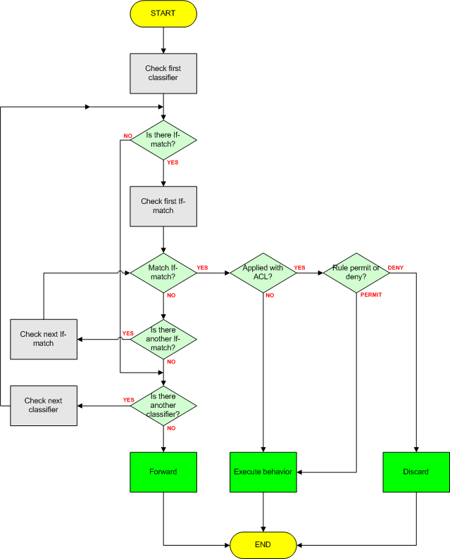
The first what a device has to do is to check if the ACL exists. If it does, the device matches packets against rules, according to the rule ID. We can configure rule IDs manually or they are automatically allocated. In case of automatically allocated rules, there is a certain space between two rule IDs. The size of the space depends on ACL step. By default it is 5 but we can change it by command. In this manner, we can add a rule before the first rule or between rules. ACL rules are displayed in ascending order of rule IDs, not in the order of configuration.

ACL rules can be arranged in two modes: configuration and auto.

In the configuration mode (default mode), we decide which rule should be first, which second and so on and so forth. In this mode, the device matches rules in ascending order of rule IDs. Anytime we can configure an additional rule with smaller rule ID. In such case, later configured rule may be matched earlier. We make such a decision, not the system.

In the auto mode, unlike in the configuration mode, the system automatically allocates rule IDs. We don’t have possibility to specify rule ID. The most precise rule is placed at the beginning of ACL.

When can we use it?

For example, if we filter a wide range of packets and want to allow some packets (from this wide range) to pass, it is enough to define a specific rule, without rules reordering. This rule will be placed first, as it is more specific.

For basic ACL rules, the source address wildcards are compared. If they are the same, then the configuration order is taken into account.

For advanced ACL rules, more factors are compared, like wildcards of source and destination and protocol ranges of source and destination.

Let’s configure the same ACL with 2 modes:

[Huawei]acl number 3000  match-order auto
[Huawei-acl-adv-3000]rule perm ip source 10.1.1.0 0.0.0.255 destination 172.16.1.0 0.0.0.255
[Huawei-acl-adv-3000]rule permit ip source 150.20.0.0 0.0.0.255 destination 10.1.0.0 0.0.0.255
[Huawei-acl-adv-3000]rule deny ip sou 10.1.1.10 0.0.0.0 destination 172.16.1.0 0.0.0.255
[Huawei-acl-adv-3000]rule den ip source 150.20.0.0 0.0.0.255 destination 10.1.0.15 0.0.0.0

[Huawei-acl-adv-3000]dis this
#
acl number 3000  match-order auto
 rule 5 deny ip source 10.1.1.10 0 destination 172.16.1.0 0.0.0.255 
 rule 10 deny ip source 150.20.0.0 0.0.0.255 destination 10.1.0.15 0 
 rule 15 permit ip source 10.1.1.0 0.0.0.255 destination 172.16.1.0 0.0.0.255 
 rule 20 permit ip source 150.20.0.0 0.0.0.255 destination 10.1.0.0 0.0.0.255 

[Huawei]acl 3000 match-order config
[Huawei-acl-adv-3000]rule perm ip source 10.1.1.0 0.0.0.255 destination 172.16.1 .0 0.0.0.255
[Huawei-acl-adv-3000]rule permit ip source 150.20.0.0 0.0.0.255 destination 10.1 .0.0 0.0.0.255
[Huawei-acl-adv-3000]rule deny ip sou 10.1.1.10 0.0.0.0 destination 172.16.1.0.0.255
[Huawei-acl-adv-3000]rule den ip source 150.20.0.0 0.0.0.255 destination 10.1.0. 15 0.0.0.0

[Huawei-acl-adv-3000]dis this
#
acl number 3000  
 rule 5 permit ip source 10.1.1.0 0.0.0.255 destination 172.16.1.0 0.0.0.255 
 rule 10 permit ip source 150.20.0.0 0.0.0.255 destination 10.1.0.0 0.0.0.255 
 rule 15 deny ip source 10.1.1.10 0 destination 172.16.1.0 0.0.0.255 
 rule 20 deny ip source 150.20.0.0 0.0.0.255 destination 10.1.0.15 0

Look at the order of these 2 ACLs. Although the order of rules was the same in both cases, the final ACLs look different.

Read More »

port security on Huawei switches

How to prevent unauthorized users from connecting their PCs to an enterprise network? How to prevent employees from connecting unauthorized devices to a LAN or moving their computers without permission?

Port Security is a Layer 2 feature, which can be enabled on an interface, to prevent devices with untrusted MAC address, from accessing a switch interface. When enabled, MAC address of the device connected to the port, is dynamically learned by the switch and stored in a memory (by default it is not aged out). Only this MAC address is then allowed to forward traffic over switch port (only one trusted MAC is allowed by default). Every different MAC address will cause the port to go into one of the following states:

  • Protect – packets coming from untrusted MAC address will be dropped,
  • Restrict – packets coming from untrusted MAC address will be dropped and SNMP trap message will be generated (default behavior),
  • Shutdown – port will be put into shutdown state.

Let’s configure  port security feature on a switch port and see, how it works.

<labnarioSW1>sys
Enter system view, return user view with Ctrl+Z.
[labnarioSW1]interface gi0/0/1
[labnarioSW1-GigabitEthernet0/0/1]port link-type access
[labnarioSW1-GigabitEthernet0/0/1]port-security enable

Generate some traffic from your PC, so that switch could learn PC’s MAC address. As you can see, my PC’s MAC address of aabb-ccdd-eeff was dynamically learned and assigned to the GigabitEthernet 0/0/1 port.

[labnarioSW1-GigabitEthernet0/0/1]display mac-address security
MAC address table of slot 0:
-------------------------------------------------------------------------------
MAC Address    VLAN/       PEVLAN CEVLAN Port            Type      LSP/LSR-ID  
               VSI/SI    MAC-Tunnel  
-------------------------------------------------------------------------------
aabb-ccdd-eeff 1           -      -      GE0/0/1         security  -           
-------------------------------------------------------------------------------
Total matching items on slot 0 displayed = 1

Let’s see what happens, when different PC with different MAC address will be connected to the same port.

<labnarioSW1>
Sep 18 2013 12:51:06-08:00 labnarioSW1 L2IFPPI/4/PORTSEC_ACTION_ALARM:OID 1.3.6.1
.4.1.2011.5.25.42.2.1.7.6 The number of MAC address on interface (6/6) GigabitEth
ernet0/0/1 reaches the limit, and the port status is : 1. (1:restrict;2:protect;3
:shutdown)

All the traffic coming from different PC is dropped by the switch. Port GigabitEthernet 0/0/1 has changed its status to restrict, only MAC address of aabb-ccdd-eeff is allowed to send traffic over this port. All the other traffic will be dropped and SNMP message will be generated.

If we want our port to go into different state than the default restrict state, we can use the following options:

[labnarioSW1-GigabitEthernet0/0/1]port-security protect-action ?
  protect    Discard packets
  restrict   Discard packets and warning
  shutdown   shutdown

It is important to note that this secure MAC address, which was learned dynamically by the switch, is stored in a switch memory and will not be aged out, but in case of the switch reload, it will disappear from memory. To avoid this, MAC address sticky can be configured. This option instructs our switch to save this MAC address to the configuration file.

[labnarioSW1-GigabitEthernet0/0/1]port-security mac-address sticky

MAC address sticky has an option to define MAC address manually. This option can be used in case when PC is not actually connected to the switch port and its MAC address cannot be dynamically learned:

[labnarioSW1-GigabitEthernet0/0/1]port-security mac-address sticky aaaa-bbbb-cccc vlan 1

[labnarioSW1-GigabitEthernet0/0/1]display mac-address security
MAC address table of slot 0:
-------------------------------------------------------------------------------
MAC Address    VLAN/       PEVLAN CEVLAN Port            Type      LSP/LSR-ID  
               VSI/SI    MAC-Tunnel  
-------------------------------------------------------------------------------
aaaa-bbbb-cccc 1           -      -      GE0/0/1         sticky    -    
-------------------------------------------------------------------------------
Total matching items on slot 0 displayed = 1

If we want to define more than one secure MAC address (this is the default behavior), we can use a command as follows:

[labnarioSW1-GigabitEthernet0/0/1]port-security max-mac-num 2

Now I can add the second secure MAC address:

[labnarioSW1-GigabitEthernet0/0/1]port-security mac-address sticky cccc-bbbb-aaaa vlan 1
[labnarioSW1-GigabitEthernet0/0/1]display mac-address security
MAC address table of slot 0:
-------------------------------------------------------------------------------
MAC Address    VLAN/       PEVLAN CEVLAN Port            Type      LSP/LSR-ID  
               VSI/SI    MAC-Tunnel  
-------------------------------------------------------------------------------
aaaa-bbbb-cccc 1           -      -      GE0/0/1         sticky    -    
cccc-bbbb-aaaa 1           -      -      GE0/0/1         sticky    -    

-------------------------------------------------------------------------------
Total matching items on slot 0 displayed = 2

The last option of the Port Security feature is aging time. By default every MAC address, learned dynamically and stored in a switch memory as a secure MAC address, will not be aged out. This default behavior can be changed and aging time can be set using the following command.

[labnarioSW1-GigabitEthernet0/0/1]port-security aging-time 2

Keep in mind, that this value represents time in minutes.

Read More »

GRE over IPSec on Huawei AR routers

If you want to recall how to configure GRE, just look at GRE on Huawei routers.

You can return to IPSec configuration, reading IPSec on Huawei AR router.

Today, I’m going to put them together and try to configure GRE over IPSec.

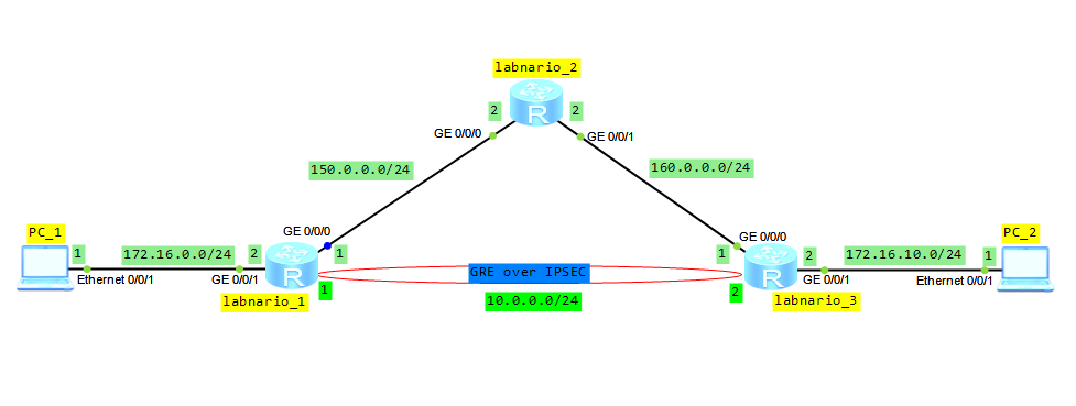
Based on the topology below, configure IP adresses and OSPF protocol to ensure connectivity between all routers (omitted here).

Configure tunnel interface on labnario_1 and labnario_3:

[labnario_1]interface Tunnel0/0/0
[labnario_1-Tunnel0/0/0] ip address 10.0.0.1 255.255.255.0 
[labnario_1-Tunnel0/0/0] tunnel-protocol gre
[labnario_1-Tunnel0/0/0] source 150.0.0.1
[labnario_1-Tunnel0/0/0] destination 160.0.0.1

[labnario_3]interface Tunnel0/0/0
[labnario_3-Tunnel0/0/0] ip address 10.0.0.2 255.255.255.0 
[labnario_3-Tunnel0/0/0] tunnel-protocol gre
[labnario_3-Tunnel0/0/0] source 160.0.0.1
[labnario_3-Tunnel0/0/0] destination 150.0.0.1

Use ping command to check if the tunnel interface has been set up:

[labnario_3]ping 150.0.0.1
  PING 150.0.0.1: 56  data bytes, press CTRL_C to break
    Request time out
    Reply from 150.0.0.1: bytes=56 Sequence=2 ttl=254 time=50 ms
    Reply from 150.0.0.1: bytes=56 Sequence=3 ttl=254 time=30 ms
    Reply from 150.0.0.1: bytes=56 Sequence=4 ttl=254 time=30 ms
    Reply from 150.0.0.1: bytes=56 Sequence=5 ttl=254 time=40 ms

  --- 150.0.0.1 ping statistics ---
    5 packet(s) transmitted
    4 packet(s) received
    20.00% packet loss
    round-trip min/avg/max = 30/37/50 ms

Configure IPSec on labnario_1 and labnario_3 (labnario_3 configuration is omitted here):

[labnario_1]acl 3500
[labnario_1-acl-adv-3500]rule permit gre source 150.0.0.1 0 destination 160.0.0.1 0
[labnario_1]ipsec proposal labnario

[labnario_1]ike local-name labnario_1

[labnario_1]ike peer labnario_3 v1
[labnario_1-ike-peer-labnario_3]exchange-mode aggressive 
[labnario_1-ike-peer-labnario_3]local-id-type name 
[labnario_1-ike-peer-labnario_3]pre-shared-key cipher labnario
[labnario_1-ike-peer-labnario_3]remote-name labnario_3
[labnario_1-ike-peer-labnario_3]remote-address 160.0.0.1 

[labnario_1]ipsec policy labnario 1 isakmp
[labnario_1-ipsec-policy-isakmp-labnario-1]security acl 3500
[labnario_1-ipsec-policy-isakmp-labnario-1]ike-peer labnario_3
[labnario_1-ipsec-policy-isakmp-labnario-1]proposal labnario 

[labnario_1-GigabitEthernet0/0/0]ipsec policy labnario

<labnario_1>dis ike sa
    Conn-ID  Peer            VPN   Flag(s)                Phase  
  ---------------------------------------------------------------
       11    160.0.0.1       0     RD|ST                  2     
       10    160.0.0.1       0     RD|ST                  1     

  Flag Description:
  RD--READY   ST--STAYALIVE   RL--REPLACED   FD--FADING   TO--TIMEOUT
  HRT--HEARTBEAT   LKG--LAST KNOWN GOOD SEQ NO.   BCK--BACKED UP

<labnario_1>dis ipsec sa

===============================
Interface: GigabitEthernet0/0/0
 Path MTU: 1500
===============================

  -----------------------------
  IPSec policy name: "labnario"
  Sequence number  : 1
  Acl Group        : 3500
  Acl rule         : 5
  Mode             : ISAKMP
  -----------------------------
    Connection ID     : 11
    Encapsulation mode: Tunnel
    Tunnel local      : 150.0.0.1
    Tunnel remote     : 160.0.0.1
    Flow source       : 150.0.0.1/255.255.255.255 47/0
    Flow destination  : 160.0.0.1/255.255.255.255 47/0
    Qos pre-classify  : Disable

    [Outbound ESP SAs] 
      SPI: 2472318789 (0x935c9745)
      Proposal: ESP-ENCRYPT-DES-64 ESP-AUTH-MD5
      SA remaining key duration (bytes/sec): 1887436800/3557
      Max sent sequence-number: 0
      UDP encapsulation used for NAT traversal: N

    [Inbound ESP SAs] 
      SPI: 3680592061 (0xdb6160bd)
      Proposal: ESP-ENCRYPT-DES-64 ESP-AUTH-MD5
      SA remaining key duration (bytes/sec): 1887436800/3557
      Max received sequence-number: 0
      Anti-replay window size: 32
      UDP encapsulation used for NAT traversal: N

Finally, configure static routes that inject traffic from PC1 and PC2 into tunnel interface:

[labnario_1]ip route-static 172.16.10.0 255.255.255.0 Tunnel0/0/0

[labnario_3]ip route-static 172.16.0.0 255.255.255.0 Tunnel0/0/0

Let’s verify whether traffic between hosts, passing through tunnel interface, is encrypted by IPSec (use ping between PC1 and PC2):

<labnario_1>dis ipsec statistics esp
 Inpacket count            : 844
 Inpacket auth count       : 0
 Inpacket decap count      : 0
 Outpacket count           : 852
 Outpacket auth count      : 0
 Outpacket encap count     : 0
 Inpacket drop count       : 0
 Outpacket drop count      : 0
 BadAuthLen count          : 0
 AuthFail count            : 0
 InSAAclCheckFail count    : 0
 PktDuplicateDrop count    : 0
 PktSeqNoTooSmallDrop count: 0
 PktInSAMissDrop count     : 0

Now we can try to spy captured packets between PCs:


Read More »