Friday , February 28 2025

PIM DM on Huawei S5700

PIM DM topology on Huawei S5700

  1. Configure IP addresses based on the above topology (omitted).
  2. Use OSPF to assure connectivity between switches.
  3. Enable multicast on both switches.
  4. Enable PIM DM on all interfaces.
  5. Address of multicast group G: 225.1.1.1.
  6. Address of multicast group S: 10.10.10.100.

OSPF configuration:

[SwitchA]dis current-configuration configuration ospf
#
ospf 1
 area 0.0.0.0
  network 10.10.30.0 0.0.0.255
  network 150.1.1.0 0.0.0.3
#
[SwitchB]display current-configuration configuration ospf
#
ospf 1
 area 0.0.0.0
  network 10.10.10.0 0.0.0.255
  network 10.10.20.0 0.0.0.255
  network 150.1.1.0 0.0.0.3
#

Although PIM is intra-domain multicast routing protocol, RPF check is always performed based on IGP, in our case OSPF. Every problem in OSPF causes a problem in the multicast.

Enable multicast on both switches:

[SwitchA]multicast routing-enable

[SwitchB]multicast routing-enable

Enable PIM DM on each interface:

[SwitchA]dis cur int Vlanif 
#
interface Vlanif300
 ip address 150.1.1.2 255.255.255.252
 pim dm
#
interface Vlanif400
 ip address 10.10.30.1 255.255.255.0
 pim dm
 igmp enable

[SwitchB]dis cur int Vlanif 
#
interface Vlanif100
 ip address 10.10.10.1 255.255.255.0
 pim dm
 igmp enable
#
interface Vlanif200
 ip address 10.10.20.1 255.255.255.0
 pim dm
 igmp enable
#
interface Vlanif300
 ip address 150.1.1.1 255.255.255.252
 pim dm
#

As you can see from the above output, except PIM DM protocol, IGMP has been configured at the interfaces towards receivers. What is IGMP? This is Internet Group Management Protocol that manages IPv4 multicast members. In short, IGMP needs to be enabled on hosts and on switches. Through IGMP, a multicast L3 device knows whether there is a multicast group member, on the network segment to which an interface of the switch is connected.

Verification (SwitchA as an example):

[SwitchA]display pim interface
 VPN-Instance: public net
 Interface           State NbrCnt HelloInt   DR-Pri     DR-Address
 Vlanif300           up    1      30         1          150.1.1.2       (local)
 Vlanif400           up    0      30         1          10.10.30.1      (local)

[SwitchA]dis pim neighbor 
 VPN-Instance: public net
 Total Number of Neighbors = 1

 Neighbor        Interface           Uptime   Expires  Dr-Priority  BFD-Session
 150.1.1.1       Vlanif300           00:57:23 00:01:22 1            N          

[SwitchA]dis igmp interface
Interface information
 Vlanif400(10.10.30.1): 
   IGMP is enabled
   Current IGMP version is 2
   IGMP state: up
   IGMP group policy: none
   IGMP limit: -
   Value of query interval for IGMP (negotiated): -
   Value of query interval for IGMP (configured): 60 s
   Value of other querier timeout for IGMP: 0 s
   Value of maximum query response time for IGMP: 10 s
   Querier for IGMP: 10.10.30.1 (this router)

Let’s start multicast source. Assume that receivers need to get information about multicast group G 225.1.1.1. When sending multicast packets to multicast group G, multicast source S 10.10.10.100 generates an SPT (shortest-path tree) through flooding and the (S, G) entries exist on both switches that are in the SPT. When a receiver joins multicast group G, an (*, G) entry is generated on the switch.

[SwitchA]dis pim routing-table
 VPN-Instance: public net
 Total 1 (*, G) entry; 1 (S, G) entry

 (*, 225.1.1.1)
     Protocol: pim-dm, Flag: WC 
     UpTime: 00:00:07
     Upstream interface: NULL
         Upstream neighbor: NULL
         RPF prime neighbor: NULL
     Downstream interface(s) information:
     Total number of downstreams: 1
         1: Vlanif400
             Protocol: igmp, UpTime: 00:00:07, Expires: never

 (10.10.10.100, 225.1.1.1)
     Protocol: pim-dm, Flag: ACT 
     UpTime: 00:12:17
     Upstream interface: Vlanif300
         Upstream neighbor: 150.1.1.1
         RPF prime neighbor: 150.1.1.1
     Downstream interface(s) information:
     Total number of downstreams: 1
         1: Vlanif400
             Protocol: pim-dm, UpTime: 00:00:07, Expires:  - 


[SwitchB]dis pim routing-table 
 VPN-Instance: public net
 Total 1 (*, G) entry; 1 (S, G) entry

 (*, 225.1.1.1)
     Protocol: pim-dm, Flag: WC 
     UpTime: 00:00:30
     Upstream interface: NULL
         Upstream neighbor: NULL
         RPF prime neighbor: NULL
     Downstream interface(s) information:
     Total number of downstreams: 1
         1: Vlanif200
             Protocol: igmp, UpTime: 00:00:30, Expires: never

 (10.10.10.100, 225.1.1.1)
     Protocol: pim-dm, Flag: LOC ACT 
     UpTime: 00:12:37
     Upstream interface: Vlanif100
         Upstream neighbor: NULL
         RPF prime neighbor: NULL
     Downstream interface(s) information:
     Total number of downstreams: 2
         1: Vlanif300
             Protocol: pim-dm, UpTime: 00:00:25, Expires: never
         2: Vlanif200
             Protocol: pim-dm, UpTime: 00:00:30, Expires:  -

Let’s check whether it works, using eNSP with VLC.

Read More »

welcome to new labnario

As you can see this post so probably new DNS servers started working correctly.

What’s new here on labnario?

In addition to a new look, a technical forum has been published. You can write your questions, describe technical problems or just talk about everything and nothing in Hyde Park category. It depends on you if this forum meets its goal. I wouldn’t like to close it due to a little activity. As I see, such a fate befalls most technical forums on the internet. I count on your activity here on the forum. Let’s build a forum of which we can be proud of.

I’m still working to properly assign links on the blog. Most of links direct you to the old blog. It will be changed ASAP.

As it was not possible to move all posts from the old blog automatically, I had to do this manually. That’s why there is a significant probability of mistakes. If you find them, just let me know.

The old blog will not be closed. You will find it on wordpress platform.

New posts will be published only here, so be invited to sign for labnario’s newsletter. You can also build our labnario community on Facebook.

What can I say?

Enjoy the new labnario.

Read More »

routing policy configuration

Some time ago I wrote about local PBR and interface PBR.

It’s time to talk about routing policy, that is a different mechanism. Routing policy is applied to routing information and it is combined with routing protocols to form policies. PBR mechanism is applied to data flows and and packets are forwarded according to the configured policy.

Routing policy is a tool which can be used to filter routes and set route attributes, when importing routing information into OSPF, RIP, ISIS or BGP protocols. BGP can use routing policy to filter advertising routes as well. Routing policy defines which of the routes from the specific routing protocol are allowed to be imported into the target routing protocol. It can be also used to match routes or certain route attributes and to change these attributes when the matching rules are met.

Routing policy command syntax:
route-policy route-policy-name { permit | deny } node node

A route-policy may consists of multiple nodes, for example:

route-policy LABNARIO-POLICY permit node 10
route-policy LABNARIO-POLICY deny node 20

The relationship between the nodes of a route-policy is „OR”. This means that if a route matches the node 10 command, the route will not be matched against the node 20. If a route does not match any node, the route fails to match the route-policy. If two nodes are configured, a route is first matched with the node 10 command.

A node in a route-policy can use:

  • permit parameter – If a route matches the node, the router performs actions defined by the apply clauses and the matching is complete. Otherwise, the route continues to match the next node.
  • deny parameter – in this mode the apply clauses are not used. If a route entry matches all the if-match clauses of the node, the route is denied by the node and the next node is not matched. If the entry does not match all the clauses, the next node is matched.

It is important to note that:

  • by default, routes that are unmatched by the nodes, will be denied
  • if multiple nodes are defined, at least one of them should use permit parameter
  • if all the nodes are in deny mode, all the routes will be denied by the route-policy
  • if no if-match clause is defined, all the routes meet the matching rules

Each node can be classified into the following clauses:

  • if-match – match certain route attributes
  • apply – set certain route attributes

The relationship between the if-match clauses is “AND”. This means that a route must match all the if-match clauses.

If-match clauses can match the following:

acl                  Specify an ACL
as-path-filter       BGP AS path list
community-filter     Match BGP community filter
cost                 Match metric of route
extcommunity-filter  Match BGP/VPN extended community filter
interface            Specify the interface matching the first hop of routes
ip                   IP information
  group-address 		Match group address of route
  next-hop      		Match next-hop address of route
  route-source  		Match advertising source address of route
ip-prefix            Specify an address prefix-list
ipv6                 IPv6 Information
  group-address 		Match group address of route
  next-hop      		Match next-hop address of route
  route-source  		Match advertising source address of route
mpls-label           Give the Label
rd-filter            Route-distinguisher filter
route-type           Match route-type of route
  external-type1       OSPF External Type 1 routes
  external-type1or2    OSPF External routes (OSPF type 1/2)
  external-type2       OSPF External Type 2 routes
  internal             Internal route (including OSPF intra/inter area)
  is-is-level-1        IS-IS Level-1 routes
  is-is-level-2        IS-IS Level-2 routes
  nssa-external-type1  OSPF NSSA External Type1 routes
  nssa-external-type1or2  OSPF NSSA External Type1 and Type2 routes
  nssa-external-type2  OSPF NSSA External Type2 routes
tag                  Match tag of route

Apply clauses can set the following:

[Labnario-route-policy]apply ?
  as-path           BGP AS path list
  backup-interface  Backup outgoing interface
  backup-nexthop    Backup nexthop address
  behavior          Specify QoS policy as behavior
  comm-filter       Set BGP community filter (for deletion)
  community         BGP community attribute
  cost              Set metric of route
  cost-type         Type of metric for destination routing protocol
    external   IS-IS external metric
    internal   IS-IS internal metric/Set BGP MED to IGP metric of nexthop
    type-1     OSPF External Type 1 routes
    type-2     OSPF External Type 2 routes
  dampening         Set BGP route flap dampening parameters
  extcommunity      Set BGP/VPN extended community filter
  ip-address        IP information
    next-hop   Next hop address
  ip-precedence     Specify QoS policy as IP precedence
  ipv6              IPv6 Information
    next-hop   Next hop address
  isis              Where to import route
    level-1    Import into a level-1 area
    level-1-2  Import into level-1 and level-2
    level-2    Import into level-2 sub-domain
  local-preference  BGP local preference path attribute
  mpls-label        Give the Label
  origin            BGP origin code
    egp        Remote EGP
    igp        Local IGP
    incomplete Unknown heritage
  ospf              Where to import route
    backbone   Import into OSPF backbone area
    stub-area  Import into OSPF NSSA area  
  preference        Give the Preference  (Route Preference)
  preferred-value   BGP Preferred-value (weight) for routing table
  qos-local-id      Specify QoS policy as qos local id
  tag               Set tag of route
  traffic-index     Specify BGP Traffic Accounting Index

Examples:

Configure a route-policy to import into OSPF:

  • routes tagged with a value of 100
  • routes tagged with a value of 200
  • set them a tag 300
  • block any other routes

Configure a route-policy to import into RIP:

  • All the OSPF routes except the prefix 120.10.1.0/24, if it comes from the source of 150.100.1.5

routing policy

Config should be done on AR1 router, as this is a boundary router between OSPF and RIP domains:

#
route-policy RIP-2-OSPF permit node 10 
 if-match tag 100
 apply tag 300
#
route-policy RIP-2-OSPF permit node 20 
 if-match tag 200
 apply tag 300
#
ospf 1
 import-route rip 1 route-policy RIP-2-OSPF

#
route-policy OSPF-2-RIP deny node 10 
 if-match ip-prefix PREFIX1 
 if-match ip route-source acl 2001 
#
route-policy OSPF-2-RIP permit node 20 
#
ip ip-prefix PREFIX1 index 10 permit 120.10.1.0 24
#
acl number 2001
 rule 10 permit source 150.100.1.5 0 
#
rip 1
 import-route ospf 1 route-policy OSPF-2-RIP

Read More »

VPN FRR on Huawei routers

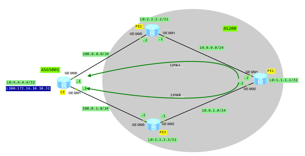
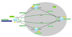
Last time IP FRR on Huawei routers was introduced. Let’s go on with VPN FRR today.

VPN FRR topology


  1. Configure IP addresses based on the topology (omitted)
  2. Configure ISIS on PE1, PE2 and PE3.
  3. Configure MPLS function on all PE routers and enable MPLS LDP to set up an LSP.
  4. Configure VPN instance on all PE devices.
  5. Configure MP-IBGP between PE routers.
  6. Configure EBGP between CE and PE2/PE3 routers.
  7. Configure VPN FRR policy on PE1.
  8. Configure BFD session between PE1 and PE2.

Configure ISIS and MPLS globally and on interfaces (PE1 as an example):

[PE1]isis
[PE1-isis-1]is-level level-2
[PE1-isis-1]network-entity 10.0010.0100.1001.00
[PE1-isis-1]
[PE1]mpls
[PE1-mpls]quit
[PE1]mpls ldp
[PE1-mpls-ldp]

[PE1]interface GigabitEthernet0/0/1
[PE1-GigabitEthernet0/0/1]isis enable
[PE1-GigabitEthernet0/0/1]mpls
[PE1-GigabitEthernet0/0/1] mpls ldp
[PE1-GigabitEthernet0/0/1]quit
[PE1]interface GigabitEthernet0/0/2
[PE1-GigabitEthernet0/0/2]isis enable
[PE1-GigabitEthernet0/0/2]mpls
[PE1-GigabitEthernet0/0/2] mpls ldp
[PE1-GigabitEthernet0/0/2]quit
[PE1]interface LoopBack0
[PE1-LoopBack0]isis enable

[PE1]dis isis peer
                          Peer information for ISIS(1)
  System Id     Interface          Circuit Id       State HoldTime Type     PRI
-------------------------------------------------------------------------------
0020.0200.2002  GE0/0/1            0020.0200.2002.01 Up   7s       L2       64 
0030.0300.3003  GE0/0/2            0030.0300.3003.01 Up   8s       L2       64 
Total Peer(s): 2

[PE1]dis mpls ldp peer
 LDP Peer Information in Public network
 A '*' before a peer means the peer is being deleted.
 ------------------------------------------------------------------------------
 PeerID                 TransportAddress   DiscoverySource
 ------------------------------------------------------------------------------
 2.2.2.2:0              2.2.2.2            GigabitEthernet0/0/1
 3.3.3.3:0              3.3.3.3            GigabitEthernet0/0/2
 ------------------------------------------------------------------------------
 TOTAL: 2 Peer(s) Found.

Configure VPN instance on all PE devices (PE1 as an example):

[PE1]ip vpn-instance labnario
[PE1-vpn-instance-labnario]route-distinguisher 200:1
[PE1-vpn-instance-labnario]vpn-target 200:200 both

Configure MP-IBGP between PE routers (PE1 as an example):

[PE1]bgp 200
[PE1-bgp]peer 2.2.2.2 as-number 200 
[PE1-bgp] peer 2.2.2.2 connect-interface LoopBack0
[PE1-bgp] peer 3.3.3.3 as-number 200 
[PE1-bgp] peer 3.3.3.3 connect-interface LoopBack0
[PE1-bgp]ipv4-family vpnv4
[PE1-bgp-af-vpnv4]policy vpn-target
[PE1-bgp-af-vpnv4]peer 2.2.2.2 enable
[PE1-bgp-af-vpnv4]peer 3.3.3.3 enable

[PE1]dis bgp vpnv4 all peer
 BGP local router ID : 10.0.0.2
 Local AS number : 200
 Total number of peers : 2		  Peers in established state : 2
  Peer            V          AS  MsgRcvd  MsgSent  OutQ  Up/Down       State Pref Rcv

  2.2.2.2         4         200       20       19     0 00:15:03 Established     4
  3.3.3.3         4         200       20       18     0 00:15:17 Established     4

Configure EBGP between CE and PE2/PE3 routers:

[PE2]bgp 200
[PE2-bgp]ipv4-family vpn-instance labnario
[PE2-bgp-labnario]peer 200.0.0.1 as-number 65001
[PE2-bgp-labnario]import-route direct

[PE3]bgp 200
[PE3-bgp]ipv4-family vpn-instance labnario
[PE3-bgp-labnario]peer 200.0.1.1 as-number 65001
[PE3-bgp-labnario]import-route direct

[CE]bgp 65001
[CE-bgp]peer 200.0.0.2 as-number 200 
[CE-bgp] peer 200.0.1.2 as-number 200 
[CE-bgp]import-route direct

[CE]dis bgp peer
 BGP local router ID : 200.0.0.1
 Local AS number : 65001
 Total number of peers : 2		  Peers in established state : 2
  Peer            V          AS  MsgRcvd  MsgSent  OutQ  Up/Down       State Pref Rcv

  200.0.0.2       4         200       26       31     0 00:22:35 Established     2
  200.0.1.2       4         200       26       31     0 00:22:35 Established     2

Let’s check IP routing table on PE1 router:

[PE1]dis ip rout vpn-instance labnario
Route Flags: R - relay, D - download to fib
------------------------------------------------------------------------------
Routing Tables: labnario
         Destinations : 6        Routes : 6        

Destination/Mask    Proto   Pre  Cost      Flags NextHop         Interface

        4.4.4.4/32  IBGP    255  0          RD   2.2.2.2         GigabitEthernet0/0/1
   172.16.10.10/32  IBGP    255  0          RD   2.2.2.2         GigabitEthernet0/0/1
      200.0.0.0/24  IBGP    255  0          RD   2.2.2.2         GigabitEthernet0/0/1
      200.0.1.0/24  IBGP    255  0          RD   3.3.3.3         GigabitEthernet0/0/2
255.255.255.255/32  Direct  0    0           D   127.0.0.1       InLoopBack0

As we can see, a network 172.16.10.10/32, advertised by CE router, is available on PE1 in VPN instance labnario, with next hop 2.2.2.2 (PE2).

[PE1]dis ip routing-table vpn-instance labnario 172.16.10.10 verbose 
Route Flags: R - relay, D - download to fib
------------------------------------------------------------------------------
Routing Table : labnario
Summary Count : 1

Destination: 172.16.10.10/32
     Protocol: IBGP             Process ID: 0
   Preference: 255                    Cost: 0
      NextHop: 2.2.2.2           Neighbour: 2.2.2.2
        State: Active Adv Relied       Age: 00h00m43s
          Tag: 0                  Priority: low
        Label: 1026                QoSInfo: 0x0
   IndirectID: 0x6              
 RelayNextHop: 10.0.0.1          Interface: GigabitEthernet0/0/1
     TunnelID: 0x1                   Flags: RD

Based on the traditional BGP/MPLS VPN technology, both PE2 and PE3 advertise the routes destined for CE to PE1, and allocate private network labels. PE1 then selects a VPNv4 route from MP-BGP neighbors according to the policy. The preferred route, in this example, is the one advertised by PE2.

In case of a fault occurs on PE2, PE1 detects the fault of PE2, re-selects the route advertised by PE3, and updates the forwarding entry. This results in the interruption of end-to-end services due to long convergence time.

Configure VPN FRR policy:

[PE1]ip ip-prefix vpn_frr index 10 permit 2.2.2.2 32

[PE1]route-policy vpn_frr permit node 10 
Info: New Sequence of this List.
[PE1-route-policy] if-match ip next-hop ip-prefix vpn_frr 
[PE1-route-policy] apply backup-nexthop 3.3.3.3

Enable VPN FRR:

[PE1]ip vpn-instance labnario
[PE1-vpn-instance-labnario]vpn frr route-policy vpn_frr

Configure BFD multi-hop detection between PE1 and PE2 (PE1 as an example):

[PE1]bfd to_pe2 bind peer-ip 2.2.2.2
[PE1-bfd-session-to_pe2] discriminator local 100
[PE1-bfd-session-to_pe2] discriminator remote 200
[PE1-bfd-session-to_pe2] commit

[PE1]dis bfd session all
--------------------------------------------------------------------------------
Local Remote     PeerIpAddr      State     Type        InterfaceName            
--------------------------------------------------------------------------------
100   200        2.2.2.2         Up        S_IP_PEER         -                  
--------------------------------------------------------------------------------
     Total UP/DOWN Session Number : 1/0

Let’s check IP routing table in VRF once again:

[PE1]dis ip routing-table vpn-instance labnario 172.16.10.10 verbose 
Route Flags: R - relay, D - download to fib
------------------------------------------------------------------------------
Routing Table : labnario
Summary Count : 1

Destination: 172.16.10.10/32
     Protocol: IBGP             Process ID: 0
   Preference: 255                    Cost: 0
      NextHop: 2.2.2.2           Neighbour: 2.2.2.2
        State: Active Adv Relied       Age: 00h05m54s
          Tag: 0                  Priority: low
        Label: 1026                QoSInfo: 0x0
   IndirectID: 0x6              
 RelayNextHop: 10.0.0.1          Interface: GigabitEthernet0/0/1
     TunnelID: 0x1                   Flags: RD
    BkNextHop: 3.3.3.3         BkInterface: GigabitEthernet0/0/2
      BkLabel: 1024            SecTunnelID: 0x0              
 BkPETunnelID: 0x3         BkPESecTunnelID: 0x0  
 BkIndirectID: 0x3

Check a backup next hop address. As you can see, loopback IP address of PE3 has been set as the backup next hop. Additionally a backup label has been specified.

VPN FRR ensures fast end-to-end convergence of services, in a VPN where CEs are dual-homed to a PE, in the case of a PE fault. VPN FRR technology is an improvement of the traditional technology. With VPN FRR, PE1 can select the appropriate VPNv4 routes according to the matching rules. For these routes, in addition to information about the preferred routes advertised by PE2, information about the second-best route advertised by PE3 is filled in the forwarding entry. When a fault occures on PE2, BFD session between PE1 and PE2 is going down. Next PE1 router detects that the outer tunnel between PE1 and PE2 is unavailable. If the LSP is unavailable, the forwarding engine uses the forwarding information of the second best route carried in the local forwarding entry to forward packets. This is how VPN FRR works.

Read More »

Huawei eNSP – news

Modified features:

  • Fixed incorrect VRRP state of Switch while using MD5 authentication mode.
  • Fixed loopback detection problem of Switch.
  • Fixed IPSEC issue of AR while using ah-esp or esp protocol if no authentication mode is on.
  • Fixed policy router+NAT issue of AR.
  • Enhanced eNSP Client stability.

A new Huawei eNSP has been released:

huawei-ensp-1-2-00-350


Read More »