Friday , February 28 2025

OSPF stub area on Huawei router

Instead of transmitting learned AS external routes, area border router, in a stub area, generates a default route and advertises the route to non-ABRs in the stub area. In short, stub area reduces entries in the routing table of ABR and the amount of routing information to be transmitted.

We have to remember that:

  • The backbone area cannot be a stub area
  • All routers in a stub area need to be configured using stub attributes
  • The ASBR cannot exist in a stub area
  • Virtual links cannot be configured in stub area.

Let’s try to configure a simple lab. We would like to see what happens if AREA1 becomes a stub area.

  1. Based on the topology, configure IP address of each interface.
  2. Enable OSPF on each router and configure basic OSPF functions
  3. Configure AREA1 as stub and and check routing information on router Gdansk.
  4. Check routing information on router Gdansk, previously stopping advertising type 3 LSA into the stub area.
OSPF basic configuration:
[Krakow]dis c c ospf
ospf 1 
 area 0.0.0.0 
  network 1.1.1.1 0.0.0.0 
  network 10.1.1.0 0.0.0.255 

[Warsaw]dis c c ospf
ospf 1 
 area 0.0.0.0 
  network 2.2.2.2 0.0.0.0 
  network 10.1.1.0 0.0.0.255 
 area 0.0.0.1 
  network 172.16.1.0 0.0.0.255 

[Gdansk]dis c c ospf
ospf 1 
 area 0.0.0.1 
  network 3.3.3.3 0.0.0.0 
  network 172.16.1.0 0.0.0.255

Configure router Krakow to import direct and static routes:

[Krakow]interface LoopBack 100
[Krakow-LoopBack100]ip address 5.5.5.5 255.255.255.255

[Krakow]int LoopBack 200
[Krakow-LoopBack200]ip address 6.6.6.6 255.255.255.255

[Krakow]ip route-static 100.100.100.0 255.255.255.0 NULL0
[Krakow]ip route-static 200.200.200.0 255.255.255.0 NULL0

[Krakow]ospf
[Krakow-ospf-1]import-route direct 
[Krakow-ospf-1]import-route static

Check routing table of router Gdansk:

[Gdansk]dis ip routing-table 
Route Flags: R - relay, D - download to fib
------------------------------------------------------------------------------
Routing Tables: Public
         Destinations : 15       Routes : 15       

Destination/Mask    Proto   Pre  Cost      Flags NextHop         Interface

        1.1.1.1/32  OSPF    10   2           D   172.16.1.1      GigabitEthernet0/0/1
        2.2.2.2/32  OSPF    10   1           D   172.16.1.1      GigabitEthernet0/0/1
        3.3.3.3/32  Direct  0    0           D   127.0.0.1       LoopBack0
        5.5.5.5/32  O_ASE   150  1           D   172.16.1.1      GigabitEthernet0/0/1
        6.6.6.6/32  O_ASE   150  1           D   172.16.1.1      GigabitEthernet0/0/1
       10.1.1.0/24  OSPF    10   2           D   172.16.1.1      GigabitEthernet0/0/1
  100.100.100.0/24  O_ASE   150  1           D   172.16.1.1      GigabitEthernet0/0/1
      127.0.0.0/8   Direct  0    0           D   127.0.0.1       InLoopBack0
      127.0.0.1/32  Direct  0    0           D   127.0.0.1       InLoopBack0
127.255.255.255/32  Direct  0    0           D   127.0.0.1       InLoopBack0
     172.16.1.0/24  Direct  0    0           D   172.16.1.2      GigabitEthernet0/0/1
     172.16.1.2/32  Direct  0    0           D   127.0.0.1       GigabitEthernet0/0/1
   172.16.1.255/32  Direct  0    0           D   127.0.0.1       GigabitEthernet0/0/1
  200.200.200.0/24  O_ASE   150  1           D   172.16.1.1      GigabitEthernet0/0/1
255.255.255.255/32  Direct  0    0           D   127.0.0.1       InLoopBack0

[Gdansk]dis ospf routing 

	 OSPF Process 1 with Router ID 3.3.3.3
		  Routing Tables 

 Routing for Network 
 Destination        Cost  Type       NextHop         AdvRouter       Area
 3.3.3.3/32         0     Stub       3.3.3.3         3.3.3.3         0.0.0.1
 172.16.1.0/24      1     Transit    172.16.1.2      3.3.3.3         0.0.0.1
 1.1.1.1/32         2     Inter-area 172.16.1.1      2.2.2.2         0.0.0.1
 2.2.2.2/32         1     Inter-area 172.16.1.1      2.2.2.2         0.0.0.1
 10.1.1.0/24        2     Inter-area 172.16.1.1      2.2.2.2         0.0.0.1

 Routing for ASEs
 Destination        Cost      Type       Tag         NextHop         AdvRouter
 5.5.5.5/32         1         Type2      1           172.16.1.1      1.1.1.1
 6.6.6.6/32         1         Type2      1           172.16.1.1      1.1.1.1
 100.100.100.0/24   1         Type2      1           172.16.1.1      1.1.1.1
 200.200.200.0/24   1         Type2      1           172.16.1.1      1.1.1.1

 Total Nets: 9  
 Intra Area: 2  Inter Area: 3  ASE: 4  NSSA: 0 

[Gdansk]dis ospf lsdb 

	 OSPF Process 1 with Router ID 3.3.3.3
		 Link State Database 

		         Area: 0.0.0.1
 Type      LinkState ID    AdvRouter          Age  Len   Sequence   Metric
 Router    2.2.2.2         2.2.2.2             69  36    80000006       1
 Router    3.3.3.3         3.3.3.3             67  48    80000007       0
 Network   172.16.1.2      3.3.3.3             67  32    80000003       0
 Sum-Net   2.2.2.2         2.2.2.2            114  28    80000003       0
 Sum-Net   10.1.1.0        2.2.2.2            114  28    80000003       1
 Sum-Net   1.1.1.1         2.2.2.2            114  28    80000003       1
 Sum-Asbr  1.1.1.1         2.2.2.2            114  28    80000003       1

		 AS External Database
 Type      LinkState ID    AdvRouter          Age  Len   Sequence   Metric
 External  6.6.6.6         1.1.1.1             38  36    80000004       1
 External  5.5.5.5         1.1.1.1             38  36    80000004       1
 External  100.100.100.0   1.1.1.1           1789  36    80000003       1
 External  10.1.1.0        1.1.1.1             38  36    80000004       1
 External  1.1.1.1         1.1.1.1             38  36    80000004       1
 External  200.200.200.0   1.1.1.1           1789  36    80000003       1

Now configure AREA1 as a stub area:

[Warsaw]ospf	
[Warsaw-ospf-1]area 1	
[Warsaw-ospf-1-area-0.0.0.1]stub 

[Gdansk]ospf
[Gdansk-ospf-1]are 1
[Gdansk-ospf-1-area-0.0.0.1]stub

Check routing table of router Gdansk again:

[Gdansk]dis ip rout
Route Flags: R - relay, D - download to fib
------------------------------------------------------------------------------
Routing Tables: Public
         Destinations : 12       Routes : 12       

Destination/Mask    Proto   Pre  Cost      Flags NextHop         Interface

        0.0.0.0/0   OSPF    10   2           D   172.16.1.1      GigabitEthernet0/0/1
        1.1.1.1/32  OSPF    10   2           D   172.16.1.1      GigabitEthernet0/0/1
        2.2.2.2/32  OSPF    10   1           D   172.16.1.1      GigabitEthernet0/0/1
        3.3.3.3/32  Direct  0    0           D   127.0.0.1       LoopBack0
       10.1.1.0/24  OSPF    10   2           D   172.16.1.1      GigabitEthernet0/0/1
      127.0.0.0/8   Direct  0    0           D   127.0.0.1       InLoopBack0
      127.0.0.1/32  Direct  0    0           D   127.0.0.1       InLoopBack0
127.255.255.255/32  Direct  0    0           D   127.0.0.1       InLoopBack0
     172.16.1.0/24  Direct  0    0           D   172.16.1.2      GigabitEthernet0/0/1
     172.16.1.2/32  Direct  0    0           D   127.0.0.1       GigabitEthernet0/0/1
   172.16.1.255/32  Direct  0    0           D   127.0.0.1       GigabitEthernet0/0/1
255.255.255.255/32  Direct  0    0           D   127.0.0.1       InLoopBack0

[Gdansk]dis ospf routing 

	 OSPF Process 1 with Router ID 3.3.3.3
		  Routing Tables 

 Routing for Network 
 Destination        Cost  Type       NextHop         AdvRouter       Area
 3.3.3.3/32         0     Stub       3.3.3.3         3.3.3.3         0.0.0.1
 172.16.1.0/24      1     Transit    172.16.1.2      3.3.3.3         0.0.0.1
 0.0.0.0/0          2     Inter-area 172.16.1.1      2.2.2.2         0.0.0.1
 1.1.1.1/32         2     Inter-area 172.16.1.1      2.2.2.2         0.0.0.1
 2.2.2.2/32         1     Inter-area 172.16.1.1      2.2.2.2         0.0.0.1
 10.1.1.0/24        2     Inter-area 172.16.1.1      2.2.2.2         0.0.0.1

 Total Nets: 6  
 Intra Area: 2  Inter Area: 4  ASE: 0  NSSA: 0 

[Gdansk]dis ospf lsdb 

	 OSPF Process 1 with Router ID 3.3.3.3
		 Link State Database 

		         Area: 0.0.0.1
 Type      LinkState ID    AdvRouter          Age  Len   Sequence   Metric
 Router    2.2.2.2         2.2.2.2             88  36    80000005       1
 Router    3.3.3.3         3.3.3.3             81  48    80000005       0
 Network   172.16.1.2      3.3.3.3             81  32    80000002       0
 Sum-Net   0.0.0.0         2.2.2.2            156  28    80000001       1
 Sum-Net   2.2.2.2         2.2.2.2            156  28    80000001       0
 Sum-Net   10.1.1.0        2.2.2.2            156  28    80000001       1
 Sum-Net   1.1.1.1         2.2.2.2            156  28    80000001       1

As you can see, in the stub area, AS external routes are invisible. Instead, there is a default route.

Let’s stop advertisement of type 3 LSAs into the stub area, on ABR (router Warsaw):

[Warsaw]ospf
[Warsaw-ospf-1]area 1
[Warsaw-ospf-1-area-0.0.0.1]stub no-summary

And check routing table of router Gdansk once again:

[Gdansk]dis ip routing-table
Route Flags: R - relay, D - download to fib
------------------------------------------------------------------------------
Routing Tables: Public
         Destinations : 9        Routes : 9        

Destination/Mask    Proto   Pre  Cost      Flags NextHop         Interface

        0.0.0.0/0   OSPF    10   2           D   172.16.1.1      GigabitEthernet0/0/1
        3.3.3.3/32  Direct  0    0           D   127.0.0.1       LoopBack0
      127.0.0.0/8   Direct  0    0           D   127.0.0.1       InLoopBack0
      127.0.0.1/32  Direct  0    0           D   127.0.0.1       InLoopBack0
127.255.255.255/32  Direct  0    0           D   127.0.0.1       InLoopBack0
     172.16.1.0/24  Direct  0    0           D   172.16.1.2      GigabitEthernet0/0/1
     172.16.1.2/32  Direct  0    0           D   127.0.0.1       GigabitEthernet0/0/1
   172.16.1.255/32  Direct  0    0           D   127.0.0.1       GigabitEthernet0/0/1
255.255.255.255/32  Direct  0    0           D   127.0.0.1       InLoopBack0

[Gdansk]dis ospf rout

	 OSPF Process 1 with Router ID 3.3.3.3
		  Routing Tables 

 Routing for Network 
 Destination        Cost  Type       NextHop         AdvRouter       Area
 3.3.3.3/32         0     Stub       3.3.3.3         3.3.3.3         0.0.0.1
 172.16.1.0/24      1     Transit    172.16.1.2      3.3.3.3         0.0.0.1
 0.0.0.0/0          2     Inter-area 172.16.1.1      2.2.2.2         0.0.0.1

 Total Nets: 3  
 Intra Area: 2  Inter Area: 1  ASE: 0  NSSA: 0 

[Gdansk]dis ospf lsdb

	 OSPF Process 1 with Router ID 3.3.3.3
		 Link State Database 

		         Area: 0.0.0.1
 Type      LinkState ID    AdvRouter          Age  Len   Sequence   Metric
 Router    2.2.2.2         2.2.2.2            114  36    80000006       1
 Router    3.3.3.3         3.3.3.3            106  48    8000000A       0
 Network   172.16.1.2      3.3.3.3            106  32    80000002       0
 Sum-Net   0.0.0.0         2.2.2.2            572  28    80000001       1

The routing entries of the stub router are further reduced and only the default route, to a destination outside the AS, is reserved.

Read More »

PIM SM on Huawei S5700

I wanted to use AR routers to prepare PIM SM lab but it turned out that there is a problem with cooperation between multicast source and AR router. Of course I am talking about network simulator eNSP. Finally I decided to use eNSP with S5700. So we have topology like in the last two posts:

  1. Configure VLANs, VLAN interfaces and IP addresses based on the topology (omitted).
  2. Configure OSPF to ensure connectivity between switches (omitted).
  3. Enable multicast on both switches.
  4. Enable PIM SM on all interfaces.
  5. Enable IGMP on receivers’ interfaces.
  6. Set static RP for both switches (Loopback0 of SwitchB).
  7. Address of multicast group G: 225.1.1.1.
  8. Address of multicast group S: 10.10.10.100.

Display IP routing tables of both switches:

[SwitchA]dis ip routing-table 
Route Flags: R - relay, D - download to fib
------------------------------------------------------------------------------
Routing Tables: Public
         Destinations : 9        Routes : 9        

Destination/Mask    Proto   Pre  Cost      Flags NextHop         Interface

        1.1.1.1/32  OSPF    10   1           D   150.1.1.1       Vlanif300
     10.10.10.0/24  OSPF    10   2           D   150.1.1.1       Vlanif300
     10.10.20.0/24  OSPF    10   2           D   150.1.1.1       Vlanif300
     10.10.30.0/24  Direct  0    0           D   10.10.30.1      Vlanif400
     10.10.30.1/32  Direct  0    0           D   127.0.0.1       Vlanif400
      127.0.0.0/8   Direct  0    0           D   127.0.0.1       InLoopBack0
      127.0.0.1/32  Direct  0    0           D   127.0.0.1       InLoopBack0
      150.1.1.0/30  Direct  0    0           D   150.1.1.2       Vlanif300
      150.1.1.2/32  Direct  0    0           D   127.0.0.1       Vlanif300

[SwitchB]dis ip routing-table 
Route Flags: R - relay, D - download to fib
------------------------------------------------------------------------------
Routing Tables: Public
         Destinations : 10       Routes : 10       

Destination/Mask    Proto   Pre  Cost      Flags NextHop         Interface

        1.1.1.1/32  Direct  0    0           D   127.0.0.1       LoopBack0
     10.10.10.0/24  Direct  0    0           D   10.10.10.1      Vlanif100
     10.10.10.1/32  Direct  0    0           D   127.0.0.1       Vlanif100
     10.10.20.0/24  Direct  0    0           D   10.10.20.1      Vlanif200
     10.10.20.1/32  Direct  0    0           D   127.0.0.1       Vlanif200
     10.10.30.0/24  OSPF    10   2           D   150.1.1.2       Vlanif300
      127.0.0.0/8   Direct  0    0           D   127.0.0.1       InLoopBack0
      127.0.0.1/32  Direct  0    0           D   127.0.0.1       InLoopBack0
      150.1.1.0/30  Direct  0    0           D   150.1.1.1       Vlanif300
      150.1.1.1/32  Direct  0    0           D   127.0.0.1       Vlanif300

Enable multicast on both switches:

[SwitchA]multicast routing-enable
[SwitchB]multicast routing-enable

Enable PIM SM on all interfaces and IGMP on receivers’ interfaces:

[SwitchA]dis cur int Vlanif 
#
interface Vlanif300
 ip address 150.1.1.2 255.255.255.252
 pim sm
#
interface Vlanif400
 ip address 10.10.30.1 255.255.255.0
 pim sm
 igmp enable
#

[SwitchB]dis cur interface Vlanif 
#
interface Vlanif100
 ip address 10.10.10.1 255.255.255.0
 pim sm
#
interface Vlanif200
 ip address 10.10.20.1 255.255.255.0
 pim sm
 igmp enable
#
interface Vlanif300
 ip address 150.1.1.1 255.255.255.252
 pim sm
#

Verify PIM and IGMP (SwitchA as an example):

[SwitchA]dis pim neighbor 
 VPN-Instance: public net
 Total Number of Neighbors = 1

 Neighbor        Interface           Uptime   Expires  Dr-Priority  BFD-Session
 150.1.1.1       Vlanif300           00:07:44 00:01:31 1            N       

[SwitchA]display pim interface 
 VPN-Instance: public net
 Interface           State NbrCnt HelloInt   DR-Pri     DR-Address
 Vlanif300           up    1      30         1          150.1.1.2       (local)
 Vlanif400           up    0      30         1          10.10.30.1      (local)

[SwitchA]dis igmp interface
Interface information
 Vlanif400(10.10.30.1): 
   IGMP is enabled
   Current IGMP version is 2
   IGMP state: up
   IGMP group policy: none
   IGMP limit: -
   Value of query interval for IGMP (negotiated): -
   Value of query interval for IGMP (configured): 60 s
   Value of other querier timeout for IGMP: 0 s
   Value of maximum query response time for IGMP: 10 s
   Querier for IGMP: 10.10.30.1 (this router)
Jul 15 2014 10:18:44.880.2-08:00 SwitchA PIM/7/NBR:(public net): PIM ver 2 HEL se
nding 150.1.1.2 -> 224.0.0.13 on Vlanif300  (P012213)
Jul 15 2014 10:18:44.880.3-08:00 SwitchA PIM/7/NBR:(public net): Option: 1, lengt
h: 2 (P012260)
Jul 15 2014 10:18:44.880.4-08:00 SwitchA PIM/7/NBR:(public net): Holdtime: 105 (P
012278)
Jul 15 2014 10:18:44.880.5-08:00 SwitchA PIM/7/NBR:(public net): Option: 19, leng
th: 4 (P012260)
Jul 15 2014 10:18:44.880.6-08:00 SwitchA PIM/7/NBR:(public net): DR priority: 1 (
P012324)
Jul 15 2014 10:18:44.880.7-08:00 SwitchA PIM/7/NBR:(public net): Option: 20, leng
th: 4 (P012260)
Jul 15 2014 10:18:44.880.8-08:00 SwitchA PIM/7/NBR:(public net): GenID: 0X9063A18
A (P012343)
Jul 15 2014 10:18:44.880.9-08:00 SwitchA PIM/7/NBR:(public net): Option: 65004, l
ength: 0 (P012260)
Jul 15 2014 10:18:44.880.10-08:00 SwitchA PIM/7/NBR:(public net): Unknown option 
value: (P012462)
Jul 15 2014 10:18:44.880.11-08:00 SwitchA PIM/7/NBR:(public net): Option: 2, leng
th: 4 (P012260)
Jul 15 2014 10:18:44.880.12-08:00 SwitchA PIM/7/NBR:(public net): Tbit: unset  (P
012300)
Jul 15 2014 10:18:44.880.13-08:00 SwitchA PIM/7/NBR:(public net): Lan delay: 500 
(P012303)
Jul 15 2014 10:18:44.880.14-08:00 SwitchA PIM/7/NBR:(public net): Override interv
al: 2500 (P012306)

PIM SM Hello


During neighbor discovery process, each PIM device sends Hello messages. Then DR election is performed, based on carrying the DR priority. The PIM device with the highest DR priority wins. If PIM devices have the same DR priority , the PIM device with the highest IP address wins. There are 2 multicast DRs:

  • multicast source DR – responsible for sending Register messages to RP (Rendezvous Point)
  • multicast receiver DR – responsible for forwarding multicast data to the group members.

Set static RP for both switches:

[SwitchA]pim 
[SwitchA-pim]static-rp 1.1.1.1

[SwitchB]pim
[SwitchB-pim]static-rp 1.1.1.1

[SwitchA-pim]display pim rp-info
 VPN-Instance: public net
 PIM SM static RP Number:1
     Static RP: 1.1.1.1

A static RP is recommended on small and mid-sized networks. A dynamic RP can be used on a large-scale network to improve network reliability and maintainability. In dynamic RP, candidate BSRs and RPs must be configured. Elected BSR collects RP information, summarizes that information into an RP-set and advertises the RP-set to the entire PIM-SM network.

When the source sends the first multicast packet to a multicast group G, the source’s DR encapsulates the multicast packet in a Register message and unicasts it to the RP. An (S, G) entry is created on the RP and source information is registered. When a new group member appears on the network, the receiver’s DR on the group member side sends a JOIN message to the RP. A (*, G) entry is created hop by hop and an RPT with the RP as the root is generated.

<SwitchA>dis pim routing-table 
 VPN-Instance: public net
 Total 1 (*, G) entry; 1 (S, G) entry

 (*, 225.1.1.1)
     RP: 1.1.1.1
     Protocol: pim-sm, Flag: WC 
     UpTime: 00:01:50
     Upstream interface: Vlanif300
         Upstream neighbor: 150.1.1.1
         RPF prime neighbor: 150.1.1.1
     Downstream interface(s) information:
     Total number of downstreams: 1
         1: Vlanif400
             Protocol: igmp, UpTime: 00:01:50, Expires: -

 (10.10.10.100, 225.1.1.1)
     RP: 1.1.1.1
     Protocol: pim-sm, Flag: SPT ACT 
     UpTime: 00:05:57
     Upstream interface: Vlanif300
         Upstream neighbor: 150.1.1.1
         RPF prime neighbor: 150.1.1.1
     Downstream interface(s) information:
     Total number of downstreams: 1
         1: Vlanif400
             Protocol: pim-sm, UpTime: 00:01:50, Expires: -

Debugging PIM and IGMP shows how RPT is created:

<SwitchA>
Jul 15 2014 11:02:17.140.1-08:00 SwitchA IGMP/7/REPORT:Received v2 report for gro
up 225.1.1.1 on interface Vlanif400(10.10.30.1) (G082859)
Jul 15 2014 11:02:17.140.2-08:00 SwitchA PIM/7/ROUT:(public net): PIM-SM: Create 
(*, 225.1.1.1) entry in mrt. (S0116518)
Jul 15 2014 11:02:17.140.3-08:00 SwitchA PIM/7/ROUT:(public net): PIM-SM: Adding 
iif Vlanif300 to (0.0.0.0, 225.1.1.1). (S014449)
Jul 15 2014 11:02:17.140.4-08:00 SwitchA PIM/7/ROUT:(public net): PIM-SM: Add oif
: Vlanif400 (10.10.30.1) for (10.10.10.100, 225.1.1.1) (S0114105)
Jul 15 2014 11:02:17.140.5-08:00 SwitchA PIM/7/ROUT:(public net): PIM-SM: Deletin
g iif 150.1.1.2 from (10.10.10.100, 225.1.1.1). (S013702)
Jul 15 2014 11:02:17.140.6-08:00 SwitchA PIM/7/ROUT:(public net): PIM-SM: Adding 
iif 150.1.1.2 to (10.10.10.100, 225.1.1.1). (S014195)
Jul 15 2014 11:02:17.140.7-08:00 SwitchA IGMP/7/EVENT:Creating group(225.1.1.1) f
or interface Vlanif400(10.10.30.1) (G014427)
Jul 15 2014 11:02:17.140.8-08:00 SwitchA IGMP/7/TIMER:Enqueue group(225.1.1.1) on
 interface Vlanif400(10.10.30.1) in group_calq. (G016648)
Jul 15 2014 11:02:17.140.9-08:00 SwitchA PIM/7/JP:(public net): PIM ver 2 JP  sen
ding 150.1.1.2 -> 224.0.0.13 on Vlanif300  (P012933)
Jul 15 2014 11:02:17.140.10-08:00 SwitchA PIM/7/JP:(public net): Upstream 150.1.1
.1, Groups 1, Holdtime 210 (P012939)
Jul 15 2014 11:02:17.140.11-08:00 SwitchA PIM/7/JP:(public net): Group: 225.1.1.1
/32 --- 2 joins 0 prune (P012949)
Jul 15 2014 11:02:17.140.12-08:00 SwitchA PIM/7/JP:(public net): Join: 1.1.1.1/32
 SWR (P012959)
Jul 15 2014 11:02:17.140.13-08:00 SwitchA PIM/7/JP:(public net): Join: 10.10.10.1
00/32 S (P012959)

When a group member and a multicast source that sends multicast data to the group appear on the network, multicast data is encapsulated in a Register message and then unicasted to the RP. The RP then forwards the multicast data along the RPT to group members. As RPT doesn’t have to be a shortest path (SPT), SPT switchover is performed. By default, the RP performs SPT switchover immediately after receiving the first Register message and the receiver’s DR performs SPT switchover immediately after receiving the first multicast packet. Then multicast packets are transmitted based on the SPT.

Read More »

PIM DM control messages

To understand how PIM DM works, just look at control messages generated.

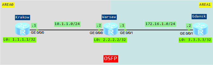
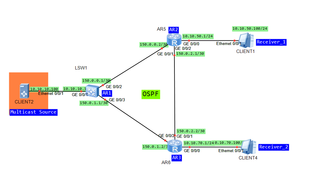
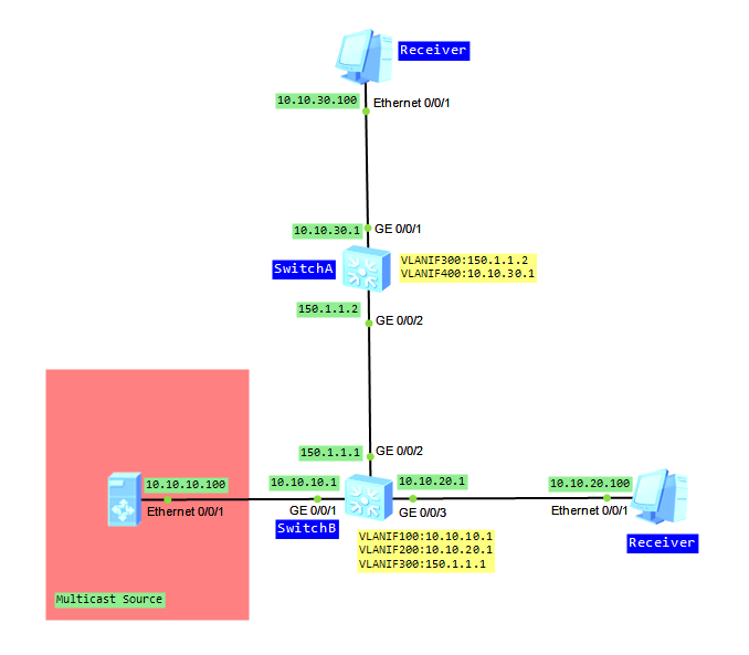
Let’s take topology from the last lab:

PIM DM topology on Huawei S5700

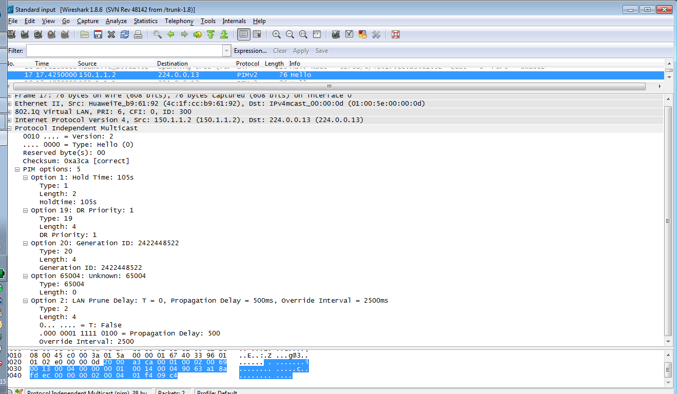
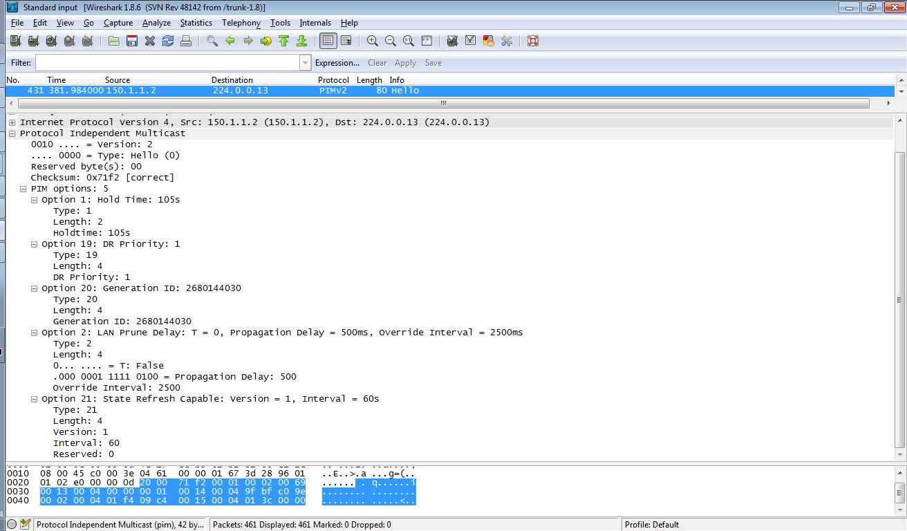
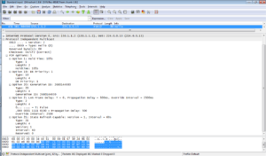
After PIM DM is configured on interfaces between neighbors, both devices periodically send HELLO messages to each other, to discover neighbors and maintain the neighbor relationship:

Jul  4 2014 13:16:44.940.2-08:00 SwitchA PIM/7/NBR:(public net): PIM ver 2 HEL se
nding 150.1.1.2 -> 224.0.0.13 on Vlanif300  (P012213)
Jul  4 2014 13:16:44.940.3-08:00 SwitchA PIM/7/NBR:(public net): Option: 1, lengt
h: 2 (P012260)
Jul  4 2014 13:16:44.940.4-08:00 SwitchA PIM/7/NBR:(public net): Holdtime: 105 (P
012278)
Jul  4 2014 13:16:44.940.5-08:00 SwitchA PIM/7/NBR:(public net): Option: 19, leng
th: 4 (P012260)
Jul  4 2014 13:16:44.940.6-08:00 SwitchA PIM/7/NBR:(public net): DR priority: 1 (
P012324)
Jul  4 2014 13:16:44.940.7-08:00 SwitchA PIM/7/NBR:(public net): Option: 20, leng
th: 4 (P012260)
Jul  4 2014 13:16:44.940.8-08:00 SwitchA PIM/7/NBR:(public net): GenID: 0X9FBFC09
E (P012343)
Jul  4 2014 13:16:44.940.9-08:00 SwitchA PIM/7/NBR:(public net): Option: 2, lengt
h: 4 (P012260)
Jul  4 2014 13:16:44.940.10-08:00 SwitchA PIM/7/NBR:(public net): Tbit: unset  (P
012300)
Jul  4 2014 13:16:44.940.11-08:00 SwitchA PIM/7/NBR:(public net): Lan delay: 500 
(P012303)
Jul  4 2014 13:16:44.940.12-08:00 SwitchA PIM/7/NBR:(public net): Override interv
al: 2500 (P012306)
Jul  4 2014 13:16:44.940.13-08:00 SwitchA PIM/7/NBR:(public net): Option: 21, len
gth: 4 (P012260)
Jul  4 2014 13:16:44.940.14-08:00 SwitchA PIM/7/NBR:(public net): Version: 1 (P01
2365)
Jul  4 2014 13:16:44.940.15-08:00 SwitchA PIM/7/NBR:(public net): Refresh interva
l: 60 (P012368)
Jul  4 2014 13:16:44.940.16-08:00 SwitchA PIM/7/NBR:(public net): Reserved: 00000

Hello

A PIM device must first receive HELLO message from its neighbor before it can receive multicast packets, to create multicast routing entries and maintain the MDT.

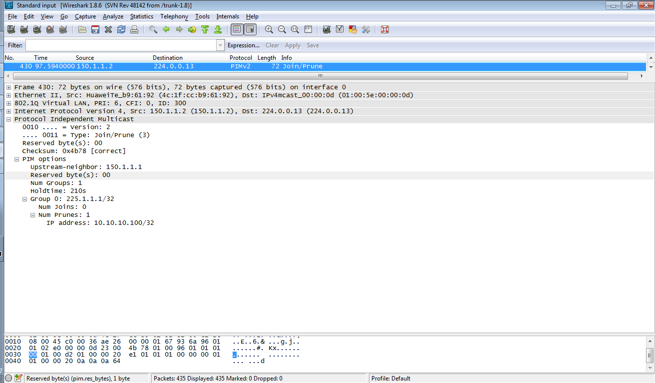
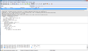
Once the PIM neighbor relationship is established, multicast source floods multicast data to all routers on the network. PIM DM assumes that at least one multicast group member exists on each subnet. That’s why all routers receive multicast data. Then PIM DM prunes brunches that don’t have multicast receivers and forward traffic only to brunches that require to receive multicast data. In such case JOIN/PRUNE message is sent by PIM router that doesn’t need multicast traffic.

Jul  4 2014 12:57:44.250.1-08:00 SwitchB PIM/7/JP:(public net): PIM ver 2 JP  rec
eiving 150.1.1.2 -> 224.0.0.13 on Vlanif300  (P012998)
Jul  4 2014 12:57:44.250.2-08:00 SwitchB PIM/7/JP:(public net): Upstream 150.1.1.
1, Groups 1, Holdtime 210 (P013002)
Jul  4 2014 12:57:44.250.3-08:00 SwitchB PIM/7/JP:(public net): Group: 225.1.1.1/
32 --- 0 join 1 prune (P013011)
Jul  4 2014 12:57:44.250.4-08:00 SwitchB PIM/7/JP:(public net): Prune: 10.10.10.1
00/32  (P013021)

At the same time network brunches send JOIN/PRUNE messages to receive multicast data. Format of this message is the same like PRUNE message.

Jul  7 2014 12:24:19.300.3-08:00 SwitchA PIM/7/JP:(public net): PIM ver 2 JP  sen
ding 150.1.1.2 -> 224.0.0.13 on Vlanif300  (P012933)
Jul  7 2014 12:24:19.300.4-08:00 SwitchA PIM/7/JP:(public net): Upstream 150.1.1.
1, Groups 1, Holdtime 0 (P012939)
Jul  7 2014 12:24:19.300.5-08:00 SwitchA PIM/7/JP:(public net): Group: 225.1.1.1/
32 --- 1 join 0 prune (P012949)
Jul  7 2014 12:24:19.300.6-08:00 SwitchA PIM/7/JP:(public net): Join: 10.10.10.10
0/32  (P012959)

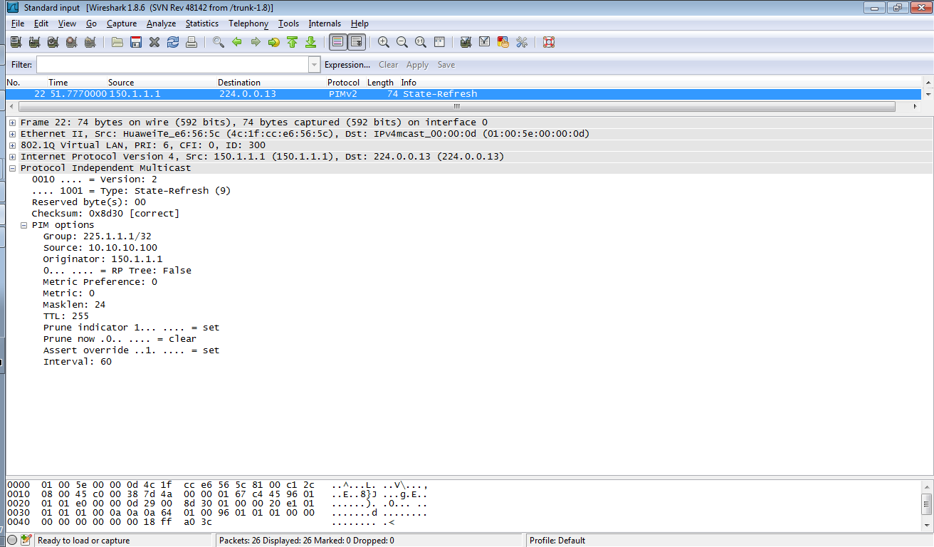
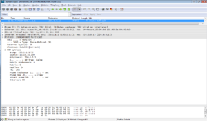
In PIM DM network, to avoid that the interface restores forwarding because the prune timer times out, the first hop router, nearest to the source, periodically triggers STATE-REFRESH messages:

Jul  7 2014 12:39:31.530.1-08:00 SwitchA PIM/7/SRM:(public net): PIM ver 2 SRM re
ceiving 150.1.1.1 -> 224.0.0.13 on Vlanif300  (D191471)
Jul  7 2014 12:39:31.530.2-08:00 SwitchA PIM/7/SRM:(public net): Group address: 2
25.1.1.1/32 flags: 00000000 (D191476)
Jul  7 2014 12:39:31.530.3-08:00 SwitchA PIM/7/SRM:(public net): Source address: 
10.10.10.100 (D191481)
Jul  7 2014 12:39:31.530.4-08:00 SwitchA PIM/7/SRM:(public net): Originator addre
ss: 150.1.1.1 (D191485)
Jul  7 2014 12:39:31.530.5-08:00 SwitchA PIM/7/SRM:(public net): preference: 0 me
tric: 0 mask length: 24  (D191514)
Jul  7 2014 12:39:31.530.6-08:00 SwitchA PIM/7/SRM:(public net): ttl: 255 prune i
ndicator: set prune now: unset assert override: set  (D191518)
Jul  7 2014 12:39:31.530.7-08:00 SwitchA PIM/7/SRM:(public net): interval: 60 (D1
91524)

state refresh

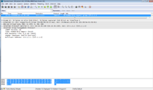
Once a receiver wants to join multicast group, it sends IGMP report to upstream device:

Jul  7 2014 13:32:45.290.1-08:00 SwitchA IGMP/7/EVENT:(S,G) creation event receiv
ed for (10.10.10.100/32, 225.1.1.1/32). (G01985)
Jul  7 2014 13:32:45.290.2-08:00 SwitchA IGMP/7/EVENT:No state in global MRT. Not
 merging downstream for (10.10.10.100/32, 225.1.1.1/32) on interface Vlanif300(15
0.1.1.2). (G011016)
Jul  7 2014 13:32:50.650.1-08:00 SwitchA IGMP/7/REPORT:Received v2 report for gro
up 225.1.1.1 on interface Vlanif400(10.10.30.1) (G082859)
Jul  7 2014 13:32:50.650.2-08:00 SwitchA IGMP/7/EVENT:Creating group(225.1.1.1) f
or interface Vlanif400(10.10.30.1) (G014427)
Jul  7 2014 13:32:50.650.3-08:00 SwitchA IGMP/7/TIMER:Enqueue group(225.1.1.1) on
 interface Vlanif400(10.10.30.1) in group_calq. (G016648)

IGMP report

After PIM router receives the report message from the host, it sends a GRAFT message through the upstream interface of the related (S, G) entry, if the router is not on the SPT (shortest path tree). Upstream device responds with GRAFT-ACK message and restores the forwarding status of the downstream interface connected to requesting device.

Jul  4 2014 12:55:53.950.1-08:00 SwitchA PIM/7/JP:(public net): PIM ver 2 GFT sen
ding 150.1.1.2 -> 150.1.1.1 on Vlanif300  (P012933)
Jul  4 2014 12:55:53.950.2-08:00 SwitchA PIM/7/JP:(public net): Upstream 150.1.1.
1, Groups 1, Holdtime 0 (P012939)
Jul  4 2014 12:55:53.950.3-08:00 SwitchA PIM/7/JP:(public net): Group: 225.1.1.1/
32 --- 1 join 0 prune (P012949)
Jul  4 2014 12:55:53.950.4-08:00 SwitchA PIM/7/JP:(public net): Join: 10.10.10.10
0/32  (P012959)
Jul  4 2014 12:55:53.960.1-08:00 SwitchA PIM/7/JP:(public net): PIM ver 2 GAK rec
eiving 150.1.1.1 -> 150.1.1.2 on Vlanif300  (P012933)
Jul  4 2014 12:55:53.960.2-08:00 SwitchA PIM/7/JP:(public net): Upstream 150.1.1.
2, Groups 1, Holdtime 0 (P012939)
Jul  4 2014 12:55:53.960.3-08:00 SwitchA PIM/7/JP:(public net): Group: 225.1.1.1/
32 --- 1 join 0 prune (P012949)
Jul  4 2014 12:55:53.960.4-08:00 SwitchA PIM/7/JP:(public net): Join: 10.10.10.10
0/32  (P012959)

PIM-DM employs GRAFT to implement fast data forwarding and enable new group members to rapidly receive multicast data.

In case of our receiver is connected to both PIM routers in our topology, in the shared network segment, the PIM device receives (S, G) packet from the downstream interface of the (S, G) or (*, G) entry. It means that other forwarders exist in the network segment. That’s why PIM device sends an ASSERT message through the downstream interface to take part in the election. The router that fails the election, stops forwarding multicast data through the downstream interface:

Jul  4 2014 15:59:43.910.2-08:00 SwitchB PIM/7/ASSERT:(public net): Fsm:assert, c
urrent state: winner received event: 10 for (10.10.10.100,225.1.1.1) on interface
 Vlanif400 (D02701)

Using debugging command and Wireshark on eNSP you can simply check how PIM DM works. You can find messages’ types, default parameters and so on. I chose only control messages, generated by PIM routers, here in this post.

Read More »

NAP – Neighbor Access Protocol

NAP is a Huawei proprietary protocol, which implements remote configuration in Layer 3 networks. It allows to log into an unconfigured device from a directly connected device. It is very simple and can be really helpful, when implementing new devices. NAP establishes a temporary neighbor relationship between configured and unconfigured devices. Both must be directly connected through a physical link. When NAP relationship is established, telnet can be done to the unconfigured device.

NAP relationship can be established in two different ways:

  • Automatically – using IP addresses allocated by the system
  • Statically – using IP addresses allocated by the administrator.

NAP cannot be used on interfaces, configured with commands affecting the IP address configuration or IP packet forwarding, such as commands related to VPNs or Ethernet trunks.

How to use NAP? Let’s assume that we have two switches as in the picture below:

Automatic NAP

Automatic NAP uses IP addresses allocated from the 10.167.253.0/24 address pool. Only one command is required to be able to telnet to unconfigured device:

<labnarioSW1>sys
Enter system view, return user view with Ctrl+Z.
[labnarioSW1]int g0/0/1
[labnarioSW1-GigabitEthernet0/0/1]nap port master
[labnarioSW1-GigabitEthernet0/0/1]quit

[labnarioSW1]dis nap status
 Slave port status         : Enable
 Nap IP-pool/Mask          : 10.167.253.0/24
[labnarioSW1-GigabitEthernet0/0/1]

[labnarioSW1-GigabitEthernet0/0/1]dis nap interface
------------------------------------------------------
 NAP master port list 
 Port count           : 1
------------------------------------------------------
 Port property                           : Master
 Current status                          : IP-ASSIGNED
 Local port                              : GigabitEthernet0/0/1
 Peer port                               : GigabitEthernet0/0/1
 Local IP                                : 10.167.253.1
 Peer IP                                 : 10.167.253.2
 Hello time                              : 3s
 Linked time                             : 00:00:22
------------------------------------------------------
 NAP slave port list  
 Port count           : 0
------------------------------------------------------

When addresses are already assigned, telnet can be done using the following command (note that this is the interface configuration view):

[labnarioSW1-GigabitEthernet0/0/1]nap login neighbor
Trying 10.167.253.2 ...
Press CTRL+K to abort
Connected to 10.167.253.2 ...

Info: The max number of VTY users is 10, and the number of current VTY users on line is 1.

Please Press ENTER.

<Huawei>sys
[Huawei]undo nap slave enable

Static NAP

Static NAP configuration requires additional command, where IP addresses assignment can be defined:

[labnarioSW1]int g0/0/1
[labnarioSW1-GigabitEthernet0/0/1]nap port master
[labnarioSW1-GigabitEthernet0/0/1]nap ip-address local 192.168.1.1 peer 192.168.1.2 24 
Are you sure to continue?[Y/N]y
[labnarioSW1-GigabitEthernet0/0/1]

[labnarioSW1]dis nap status
 Slave port status         : Enable
 Nap IP-pool/Mask          : 10.167.253.0/24

[labnarioSW1-GigabitEthernet0/0/1]dis nap interface
------------------------------------------------------
 NAP master port list 
 Port count           : 1
------------------------------------------------------
 Port property                           : Master
 Current status                          : IP-ASSIGNED
 Local port                              : GigabitEthernet0/0/1
 Peer port                               : GigabitEthernet0/0/1
 Local IP                                : 192.168.1.1
 Peer IP                                 : 192.168.1.2
 Hello time                              : 3s
 Linked time                             : 00:02:21
------------------------------------------------------
 NAP slave port list  
 Port count           : 0
------------------------------------------------------

[labnarioSW1-GigabitEthernet0/0/1]nap login neighbor
Trying 192.168.1.2 ...
Press CTRL+K to abort
Connected to 192.168.1.2 ...

Info: The max number of VTY users is 10, and the number of current VTY users on line is 1.

Please Press ENTER.

<Huawei>sys
[Huawei]undo nap slave enable

For troubleshooting use a debugging command:

<labnarioSW1>debugging nap

Read More »