Friday , February 28 2025

DHCP IPv4 server on Huawei USG6000 firewall

You know how to configure DHCP on Huawei router but have problem to do so on Huawei firewall? Take a few minutes and see how to do that.

DHCP IPv4 server that uses interface’s address pool to allocate IPv4 addresses to DHCP clients. The simplest way to implement DHCP on USG6000.

USG firewall configuration script:

#
dhcp enable
#
interface GigabitEthernet1/0/0
undo shutdown
ip address 10.0.0.1 255.255.255.0
service-manage ping permit
dhcp select interface
dhcp server excluded-ip-address 10.0.0.100
dhcp server static-bind ip-address 10.0.0.200 mac-address 5489-98b4-6a79
dhcp server dns-list 10.0.0.100
#
firewall zone trust
set priority 85
add interface GigabitEthernet1/0/0
#
security-policy
rule name ALLOW
action permit
#

Read More »

Three ways to log into eNSP emulated devices

A reminder for those who already know, a guide for those who would like to know. My first video on how to access emulated eNSP devices, including graphical access to the USG firewall. Hope you like it 🙂

Read More »

fun with wildcard mask on Huawei device

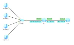
You, as the network administrator, were tasked with providing access to a network, where 4 machines have been connected.

It is simple task. Nothing can happen, but…

Everything is ready and you are checking connectivity between RT2 and those machines, and… To your suprise, you can only ping even-numbered IP addresses:

[RT2]ping 192.168.10.1
   PING 192.168.10.1: 56  data bytes, press CTRL_C to break
     Request time out
     Request time out
     Request time out
     Request time out
     Request time out

 [RT2]ping 192.168.10.2
   PING 192.168.10.2: 56  data bytes, press CTRL_C to break
     Reply from 192.168.10.2: bytes=56 Sequence=1 ttl=127 time=30 ms
     Reply from 192.168.10.2: bytes=56 Sequence=2 ttl=127 time=20 ms
     Reply from 192.168.10.2: bytes=56 Sequence=3 ttl=127 time=30 ms
     Reply from 192.168.10.2: bytes=56 Sequence=4 ttl=127 time=40 ms
     Reply from 192.168.10.2: bytes=56 Sequence=5 ttl=127 time=30 ms

 [RT2]ping 192.168.10.3
   PING 192.168.10.3: 56  data bytes, press CTRL_C to break
     Request time out
     Request time out
     Request time out
     Request time out
     Request time out

 [RT2]ping 192.168.10.4
   PING 192.168.10.4: 56  data bytes, press CTRL_C to break
     Reply from 192.168.10.4: bytes=56 Sequence=1 ttl=127 time=30 ms
     Reply from 192.168.10.4: bytes=56 Sequence=2 ttl=127 time=40 ms
     Reply from 192.168.10.4: bytes=56 Sequence=3 ttl=127 time=30 ms
     Reply from 192.168.10.4: bytes=56 Sequence=4 ttl=127 time=30 ms
     Reply from 192.168.10.4: bytes=56 Sequence=5 ttl=127 time=30 ms

What has happend?

You are sure that IP addresses and GW of PCs are correct. Let’s look into configuration of RT1 and RT2:

[RT2]
 #
 interface GigabitEthernet0/0/1
  ip address 10.0.0.2 255.255.255.0 
 #
 ip route-static 192.168.10.0 255.255.255.0 10.0.0.1

[RT1]
 #
 interface GigabitEthernet0/0/0
  ip address 192.168.10.254 255.255.255.0 
  traffic-filter inbound acl 3000
 #
 interface GigabitEthernet0/0/1
  ip address 10.0.0.1 255.255.255.0 

Everything seems to be OK. The only thing we should check is the access list number 3000. So let’s get to the ACL:

[RT1]display acl 3000
 Advanced ACL 3000, 2 rules
 Acl's step is 5
  rule 10 permit ip source 192.168.10.0 0.0.0.254 (20 matches)
  rule 15 deny ip (20 matches)

And we have a reason for the problem.

What is happening here? Let’s try to compare the IP address and the wildcard mask. Write them in binary:

11000000.10101000.00001010.00000000
00000000.00000000.00000000.11111110

We don’t care about the first 3 octects, as the bit in wildcard mask is 0. We have to focus on the last octet.

In our access list, the first seven bits of the last octet are all 1s. It means that the seven bits can be anything. The final bit in the last octet of our wildcard mask is 0. So, the very last bit in any IP address coming into this interface always has to be zero. The rest of the bits in that final octet can be anything.

What does this mean in practice?

It means that we can ping only IP addresses with the last bit 0. So we can only ping even-numbered IP addresses.

What if you want to ping only odd-numbered IP addresses. Nothing easier, just start the IP address in ACL at an odd number :

#
 acl number 3000  
  rule 10 permit ip source 192.168.10.1 0.0.0.254 
  rule 15 deny ip 
 #

Anyway, can you imagine the following wildcard mask: 0.0.255.0? What would happen if you used it with 10.10.0.1/24 IP address?

Finally you could have access to 10.10.0.1, 10.10.1.1, 10.10.2.1 and so on. How to use it in practice?

Assume that you use 10.10.0.0/16 subnet accross you entire network. You can split it to many /24 subnets. On each subnet there is a machine with the IP address 10.10.x.100 which is acting as a server offering the same functionality on each subnet. So you want to have access only to those machines, I mean 10.10.0.100, 10.10.1.100, 10.10.2.100…

To achive this goal, just configure the ACL like below:

 #
 acl number 3000  
  rule 10 permit ip source 10.10.0.100 0.0.255.0 
  rule 15 deny ip 
 # 

This article shows how powerful the wildcard mask can be. You can actually do interesting stuff with it, can’t you?

Read More »

QinQ termination on subinterfaces to support DHCP Relay

So far you have learned basic and selective QinQ on Huawei swiches. They seem like a simple Layer 2 VPN solution, which we can use to connect 2 or more offices. And of course, it is truth.

But, sometimes, we want to have an access to external services or just to the Internet, instead of connecting 2 branch offices. And, still we can use QinQ technology, why not?

The only thing we should do is to terminate QinQ VLAN Tag on a router. Just create L3 subinterface and let the router to use IP routing table to forward packets.

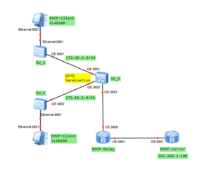
In our LAB, I am going to show you how to terminate QinQ to use DHCP server, located outside our network. In this case DHCP Relay feature must be used.

So let’s get to the point!

QinQ termination on subinterfaces to support DHCP Relay on Huawei

Topology of QinQ to support DHCP Relay

QinQ VLAN Tag termination on Huawei

1. Configure the basic Layer 2 forwarding function

SW_1
vlan batch 100
#
interface Ethernet0/0/1
 port link-type access
 port default vlan 100
#
interface GigabitEthernet0/0/1
 port link-type trunk
 port trunk allow-pass vlan 100

SW2
vlan batch 200
#
interface Ethernet0/0/1
 port link-type access
 port default vlan 200
#
interface GigabitEthernet0/0/2
 port link-type trunk
 port trunk allow-pass vlan 200

2. Configure QinQ on SW_A and set packets sent from SW_1 and SW_2 to DHCP server to carry double tags

SW_A
#
interface GigabitEthernet0/0/1
 qinq vlan-translation enable
 port hybrid untagged vlan 1000
 port vlan-stacking vlan 100 stack-vlan 1000
#
interface GigabitEthernet0/0/2
 qinq vlan-translation enable
 port hybrid untagged vlan 1000
 port vlan-stacking vlan 200 stack-vlan 1000
#
interface GigabitEthernet0/0/3
 port link-type trunk
 port trunk allow-pass vlan 1000

3. Configure subinterfaces for QinQ VLAN tag termination on the DHCP-Relay router

#
interface GigabitEthernet0/0/0.1
 qinq termination pe-vid 1000 ce-vid 100
 ip address 172.16.1.1 255.255.255.0 
 arp broadcast enable
#
interface GigabitEthernet0/0/0.2
 qinq termination pe-vid 1000 ce-vid 200
 ip address 172.16.2.1 255.255.255.0 
 arp broadcast enable

4. Configure DHCP Relay function on Huawei

[DHCP-Relay]dhcp enable

[DHCP-Relay]interface GigabitEthernet0/0/0.1
[DHCP-Relay-GigabitEthernet0/0/0.1]dhcp select relay
[DHCP-Relay-GigabitEthernet0/0/0.1]dhcp relay server-ip 192.168.1.100

[DHCP-Relay]interface GigabitEthernet0/0/0.2
[DHCP-Relay-GigabitEthernet0/0/0.1]dhcp select relay
[DHCP-Relay-GigabitEthernet0/0/0.1]dhcp relay server-ip 192.168.1.100

5. Set IP address for communication between DHCP-Relay and DHCP-Server

[DHCP-Relay]interface GigabitEthernet0/0/1
[DHCP-Relay-GigabitEthernet0/0/1]ip address 192.168.1.1 255.255.255.0

6. DHCP Server configuration

dhcp enable
#
ip pool 1
 gateway-list 172.16.1.1 
 network 172.16.1.0 mask 255.255.255.0 
#
ip pool 2
 gateway-list 172.16.2.1 
 network 172.16.2.0 mask 255.255.255.0 
#
interface GigabitEthernet0/0/1
 ip address 192.168.1.100 255.255.255.0 
 dhcp select global

7. Configure static route to reach VLAN 100 and VLAN 200

[DHCP-Server]ip route-static 172.16.1.0 255.255.255.0 192.168.1.1
[DHCP-Server]ip route-static 172.16.2.0 255.255.255.0 192.168.1.1

8. DHCP verification

[DHCP-Relay]dis dhcp relay all
 DHCP relay agent running information of interface GigabitEthernet0/0/0.1 :
 Server IP address [01] : 192.168.1.100
 Gateway address in use : 172.16.1.1
 
 DHCP relay agent running information of interface GigabitEthernet0/0/0.2 :
 Server IP address [01] : 192.168.1.100
 Gateway address in use : 172.16.2.1

9. QinQ verification

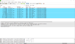
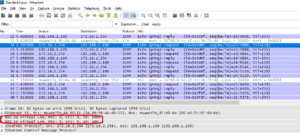
And finally, after QinQ VLAN Tag termination, we have pure IP packet without any tag:

Read More »

selective QinQ on Huawei switches

Let’s go ahead with QinQ technology. In the last post you had the opportunity to know basic QinQ tunneling on Huawei switches. The QinQ tunnel attaches the same outer tag to all the frames entering the Layer 2 QinQ interface.

In this lab I would like to attach different outer tags, to the frames entering the Layer 2 QinQ interface, according to different inner tags. It is useful when packets are going to be differentiated in a provider’s network. Why? Because of service type, user’s application etc.

In this case we have 1 enterprise network with branch office located in another city. Customer network is divided into 2 VLANs to differentiate existing services. Our task is to transparently transmit packets, through ISP network, paying attantion to not allowing traffic between VLAN10 and VLAN20.

Selective QinQ topology

Selective QinQ configuration on Huawei switches

1. First of all, configuration of switches in HQ and branch office of the enterprise.

vlan batch 10 20
#
interface Ethernet0/0/1
 port link-type access
 port default vlan 10
#
interface Ethernet0/0/2
 port link-type access
 port default vlan 20
#
interface GigabitEthernet0/0/1
 port hybrid tagged vlan 10 20

2. Farthermore, create VLANs 100 and 200 on all ISP switches. Below SwitchA as an example.

[Switch_A]vlan batch 100 200

3. Allow VLANs 100 and 200 to be transmitted between ISP switches.

[SwitchA]interface GigabitEthernet 0/0/2 
[SwitchA-GigabitEthernet0/0/2]port link-type trunk 
[SwitchA-GigabitEthernet0/0/2]port trunk allow-pass vlan 100 200 
[SwitchB]interface GigabitEthernet 0/0/4 
[SwitchB-GigabitEthernet0/0/4]port link-type trunk 
[SwitchB-GigabitEthernet0/0/4]port trunk allow-pass vlan 100 200 
[ISP]interface GigabitEthernet 0/0/2 
[ISP-GigabitEthernet0/0/2]port link-type trunk 
[ISP-GigabitEthernet0/0/2]port trunk allow-pass vlan 100 200 
[ISP]interface GigabitEthernet 0/0/4 
[ISP-GigabitEthernet0/0/4]port link-type trunk 
[ISP-GigabitEthernet0/0/4]port trunk allow-pass vlan 100 200

4. Configure selective QinQ on interfaces of SwitchA and SwitchB.

[Switch_A]interface GigabitEthernet 0/0/1
[Switch_A-GigabitEthernet0/0/1]qinq vlan-translation enable
[Switch_A-GigabitEthernet0/0/1] port hybrid untagged vlan 100 200
[Switch_A-GigabitEthernet0/0/1] port vlan-stacking vlan 10 stack-vlan 100
[Switch_A-GigabitEthernet0/0/1] port vlan-stacking vlan 20 stack-vlan 200
[Switch_B]interface GigabitEthernet 0/0/1
[Switch_B-GigabitEthernet0/0/1]qinq vlan-translation enable 
[Switch_B-GigabitEthernet0/0/1] port hybrid untagged vlan 100 200 
[Switch_B-GigabitEthernet0/0/1] port vlan-stacking vlan 10 stack-vlan 100 
[Switch_B-GigabitEthernet0/0/1] port vlan-stacking vlan 20 stack-vlan 200

Please notice that selective QinQ can only be enabled on hybrid interfaces and is valid only for incoming packets. Outer VLAN tags will be removed from outgoing frames and transmitted as 802.1Q towards enterprise switches.

5. Check communication between PCs in the same VLANs.

PC_VLAN10>ping 172.16.10.2

Ping 172.16.10.2: 32 data bytes, Press Ctrl_C to break
From 172.16.10.2: bytes=32 seq=1 ttl=128 time=125 ms
From 172.16.10.2: bytes=32 seq=2 ttl=128 time=141 ms
From 172.16.10.2: bytes=32 seq=3 ttl=128 time=156 ms
From 172.16.10.2: bytes=32 seq=4 ttl=128 time=94 ms
From 172.16.10.2: bytes=32 seq=5 ttl=128 time=141 ms
PC_VLAN20>ping 172.16.20.2

Ping 172.16.20.2: 32 data bytes, Press Ctrl_C to break
From 172.16.20.2: bytes=32 seq=1 ttl=128 time=125 ms
From 172.16.20.2: bytes=32 seq=2 ttl=128 time=125 ms
From 172.16.20.2: bytes=32 seq=3 ttl=128 time=141 ms
From 172.16.20.2: bytes=32 seq=4 ttl=128 time=156 ms
From 172.16.20.2: bytes=32 seq=5 ttl=128 time=187 ms

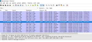
Let’s look into ICMP packet traveling through ISP network:

And finally, communication between VLANs is blocked as we assumed.

PC_VLAN10>ping 172.16.20.2

Ping 172.16.20.2: 32 data bytes, Press Ctrl_C to break
From 172.16.10.1: Destination host unreachable

Read More »