Generic Routing Encapsulation (GRE) is introduced to encapsulate packets. Then these packets can be transmitted over an IPv4 network. GRE provides a mechanism to encapsulate packets of one protocol into packets of another protocol. This allows packets to be transmitted over heterogeneous networks. GRE also provides tunnels to transparently transmit VPN packets. When a device receives a packet that needs to be encapsulated and routed, it adds a GRE header to the packet and encapsulates it into another protocol such as IP. The packet is then forwarded by the IP protocol.
Let’s try to configure GRE tunnel between labnario_1 and labnario_3. All packets sent from PC_1 to PC_2, and vice versa, will be transmitted through the GRE tunnel.
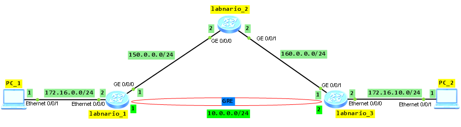
Assure communication between routers in the network. It is omitted here.
Create a tunnel interface with tunnel-protocol as GRE on both labnario_1 and labnario_3 routers. Assign IP address of tunnel interface and IP addresses of tunnel’s source and destination:
[labnario_1]interface Tunnel 0/0/0
[labnario_1-Tunnel0/0/0]ip address 10.0.0.1 255.255.255.0
[labnario_1-Tunnel0/0/0] tunnel-protocol gre
[labnario_1-Tunnel0/0/0] source 150.0.0.1
[labnario_1-Tunnel0/0/0] destination 160.0.0.1

[labnario_3]interface Tunnel 0/0/0
[labnario_3-Tunnel0/0/0]ip address 10.0.0.2 255.255.255.0
[labnario_3-Tunnel0/0/0] tunnel-protocol gre
[labnario_3-Tunnel0/0/0] source 160.0.0.1
[labnario_3-Tunnel0/0/0] destination 150.0.0.1
Configure static routing on labnario_1 and labnario_3 to PC_2 and PC_1 respectively, with GRE tunnel as outbound interface. This ensures that all traffic directed to those PCs will be going through GRE tunnel interface.
[labnario_1]ip route-static 172.16.10.0 255.255.255.0 Tunnel0/0/0

[labnario_3]ip route-static 172.16.0.0 255.255.255.0 Tunnel0/0/0
Check routing tables of both routers:
[labnario_1]display ip routing-table
Route Flags: R - relay, D - download to fib
------------------------------------------------------------------------------
Routing Tables: Public
         Destinations : 10       Routes : 10

Destination/Mask    Proto   Pre  Cost  Flags NextHop         Interface

       10.0.0.0/24  Direct  0    0       D   10.0.0.1        Tunnel0/0/0
       10.0.0.1/32  Direct  0    0       D   127.0.0.1       Tunnel0/0/0
      127.0.0.0/8   Direct  0    0       D   127.0.0.1       InLoopBack0
      127.0.0.1/32  Direct  0    0       D   127.0.0.1       InLoopBack0
      150.0.0.0/24  Direct  0    0       D   150.0.0.1       GigabitEthernet0/0/0
      150.0.0.1/32  Direct  0    0       D   127.0.0.1       GigabitEthernet0/0/0
      160.0.0.0/24  OSPF    10   2       D   150.0.0.2       GigabitEthernet0/0/0
     172.16.0.0/24  Direct  0    0       D   172.16.0.2      Ethernet0/0/0
     172.16.0.2/32  Direct  0    0       D   127.0.0.1       Ethernet0/0/0
    172.16.10.0/24  Static  60   0       D   10.0.0.1        Tunnel0/0/0

[labnario_3]display ip routing-table
Route Flags: R - relay, D - download to fib
------------------------------------------------------------------------------
Routing Tables: Public
         Destinations : 10       Routes : 10

Destination/Mask    Proto   Pre  Cost   Flags NextHop         Interface

       10.0.0.0/24  Direct  0    0        D   10.0.0.2        Tunnel0/0/0
       10.0.0.2/32  Direct  0    0        D   127.0.0.1       Tunnel0/0/0
      127.0.0.0/8   Direct  0    0        D   127.0.0.1       InLoopBack0
      127.0.0.1/32  Direct  0    0        D   127.0.0.1       InLoopBack0
      150.0.0.0/24  OSPF    10   2        D   160.0.0.2       GigabitEthernet0/0/1
      160.0.0.0/24  Direct  0    0        D   160.0.0.1       GigabitEthernet0/0/1
      160.0.0.1/32  Direct  0    0        D   127.0.0.1       GigabitEthernet0/0/1
     172.16.0.0/24  Static  60   0        D   10.0.0.2        Tunnel0/0/0
    172.16.10.0/24  Direct  0    0        D   172.16.10.2     Ethernet0/0/0
    172.16.10.2/32  Direct  0    0        D   127.0.0.1       Ethernet0/0/0
Let’s check if traffic is going through GRE tunnel:
PC_1>ping 172.16.10.1 -t

Ping 172.16.10.1: 32 data bytes, Press Ctrl_C to break
From 172.16.10.1: bytes=32 seq=1 ttl=126 time=31 ms
From 172.16.10.1: bytes=32 seq=2 ttl=126 time=78 ms
From 172.16.10.1: bytes=32 seq=3 ttl=126 time=78 ms
From 172.16.10.1: bytes=32 seq=4 ttl=126 time=63 ms
From 172.16.10.1: bytes=32 seq=5 ttl=126 time=94 ms
From 172.16.10.1: bytes=32 seq=6 ttl=126 time=78 ms
From 172.16.10.1: bytes=32 seq=7 ttl=126 time=62 ms
From 172.16.10.1: bytes=32 seq=8 ttl=126 time=32 ms
From 172.16.10.1: bytes=32 seq=9 ttl=126 time=93 ms
From 172.16.10.1: bytes=32 seq=10 ttl=126 time=78 ms

--- 172.16.10.1 ping statistics ---
  10 packet(s) transmitted
  10 packet(s) received
  0.00% packet loss
  round-trip min/avg/max = 31/67/94 ms

[labnario_1]display interface Tunnel 0/0/0
Tunnel0/0/0 current state : UP
Line protocol current state : UP
Last line protocol up time : 2013-01-28 13:22:16 UTC-08:00
Description:
Route Port,The Maximum Transmit Unit is 1500
Internet Address is 10.0.0.1/24
Encapsulation is TUNNEL, loopback not set
Tunnel source 150.0.0.1 (GigabitEthernet0/0/0), destination 160.0.0.1
Tunnel protocol/transport GRE/IP, key disabled
keepalive disabled
Checksumming of packets disabled
Current system time: 2013-01-28 13:22:59-08:00
    300 seconds input rate 0 bits/sec, 0 packets/sec
    300 seconds output rate 0 bits/sec, 0 packets/sec
    49 seconds input rate 136 bits/sec, 0 packets/sec
    49 seconds output rate 136 bits/sec, 0 packets/sec
    10 packets input,  840 bytes
    0 input error
    10 packets output,  840 bytes
    0 output error
    Input:
      Unicast: 0 packets, Multicast: 0 packets
    Output:
      Unicast: 10 packets, Multicast: 0 packets
    Input bandwidth utilization  : --
    Output bandwidth utilization : --
Use debugging for GRE verification:
<labnario_1>debugging tunnel ?
  all        All debugging functions
  control    Control debugging function
  error      Error debugging function
  keepalive  GRE keepalive debugging function
  packet     Packet debugging function
  timer      Timer debugging function

<labnario_3>debugging tunnel all
<labnario_3>t m
Info: Current terminal monitor is on.
<labnario_3>t d
Info: Current terminal debugging is on.

Jan 28 2013 12:25:04.340.3-08:00 labnario_1 TUNNEL/7/debug:GRE_FWD: Tunnel0/0/0-Out:GRE/IP encapsulated 150.0.0.1->160.0.0.1(len = 84).
Jan 28 2013 12:25:04.340.4-08:00 labnario_1 TUNNEL/7/debug:GRE_FWD: GRE Transmit: Transmit packets through IP output sucessfully.
Jan 28 2013 12:25:04.400.1-08:00 labnario_1 TUNNEL/7/debug:GRE_FWD:GRE-Input: Src(160.0.0.1)/dest(150.0.0.1), length = 84.
Jan 28 2013 12:25:04.400.2-08:00 labnario_1 TUNNEL/7/debug:GRE_FWD: Get packet without checksum.
Jan 28 2013 12:25:04.400.3-08:00 labnario_1 TUNNEL/7/debug:GRE_FWD: Tunnel0/0/0-In: GRE decapsulated IP source(172.16.10.1)/destination(172.16.0.1)(len = 60).
Jan 28 2013 12:25:04.400.4-08:00 labnario_1 TUNNEL/7/debug:GRE_FWD: Put packets into IP queue sucessfully.
Jan 28 2013 12:25:05.400.1-08:00 labnario_1 TUNNEL/7/debug:GRE_FWD: GRE-Encapsulation: Mbuf length = 60 from Tunnel0/0/0 out.
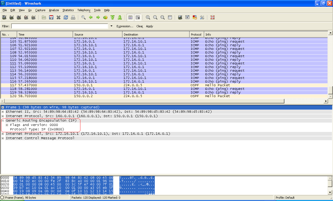
Packet capture output from interface GE0/0/0 of labnario_1:
Final configs:
sysname labnario_1
#
interface Ethernet0/0/0
 ip address 172.16.0.2 255.255.255.0
#
interface GigabitEthernet0/0/0
 ip address 150.0.0.1 255.255.255.0
#
interface Tunnel0/0/0
 ip address 10.0.0.1 255.255.255.0
 tunnel-protocol gre
 source 150.0.0.1
 destination 160.0.0.1
#
ospf 1
 area 0.0.0.0
  network 150.0.0.0 0.0.0.255
#
ip route-static 172.16.10.0 255.255.255.0 Tunnel0/0/0

sysname labnario_2
#
interface GigabitEthernet0/0/0
 ip address 150.0.0.2 255.255.255.0
#
interface GigabitEthernet0/0/1
 ip address 160.0.0.2 255.255.255.0
#
ospf 1
 area 0.0.0.0
  network 150.0.0.0 0.0.0.255
  network 160.0.0.0 0.0.0.255

sysname labnario_3
#
interface Ethernet0/0/0
 ip address 172.16.10.2 255.255.255.0
#
interface GigabitEthernet0/0/1
 ip address 160.0.0.1 255.255.255.0
#
interface Tunnel0/0/0
 ip address 10.0.0.2 255.255.255.0
 tunnel-protocol gre
 source 160.0.0.1
 destination 150.0.0.1
#
ospf 1
 area 0.0.0.0
  network 160.0.0.0 0.0.0.255
#
ip route-static 172.16.0.0 255.255.255.0 Tunnel0/0/0
Read More »