Friday , February 28 2025

how to upgrade stacked S5300 switches

When a single switch is upgraded, services are interrupted about 3 minutes. This time increases when a stack is upgraded. Methods of upgrading the system software of S5300 and S6300 are the same. We can focus on Huawei S5300 switch as an example. Let’s assume we have 2 switches in the stack.

<labnario> display stack
Stack topology type: Ring
Stack system MAC: 80fb-06b1-69eb
MAC switch delay time: 10 min
Stack reserved vlanid : 100
Slot#     role        Mac address      Priority   Device type
------    ----        --------------   ------     -------
    0     Master      80fb-06b1-69eb   100        S5352C-EI
    1     Standby     80fb-06ab-f6e3   120        S5352C-EI

At first you have to check a space of flash memory of the switch. If there is no enough space in the flash to fit a new system software, just delete the old (current) system software, for both Master and Member switches:

<labnario> delete /unreserved flash:/S5300EI-V100R005C00SPC100.cc
Info:This is Next startup system software.If you delete it,there is no software to reboot successfully!Confirm to delete the file? [Y/N]:y
Warning: The contents of file flash:/S5300EI-V100R005C00SPC100.cc cannot be recycled. Continue? [Y/N]:y
Info: Deleting file flash:/S5300EI-V100R005C00SPC100.cc...
Deleting file permanently from flash will take a long time if needed................succeeded.
<labnario> delete /unreserved slot1#flash:/S5300EI-V100R005C00SPC100.cc
Info:This is Next startup system software.If you delete it,there is no software to reboot successfully!Confirm to delete the file? [Y/N]:y
Warning: The contents of file slot1#flash:/S5300EI-V100R005C00SPC100.cc cannot be recycled. Continue? [Y/N]:y
Info: Deleting file slot1#flash:/S5300EI-V100R005C00SPC100.cc...
Deleting file permanently from flash will take a long time if needed................succeeded.

Upload a new software to Master switch. If you do not remember how to do this, just go to upgrade of huawei’s S5300 switch.

Specify the uploaded software as the next startup software. As you can see the new software is copied to Member switch automatically. You have an answer now, why upgrading time of stack switches increases, comparing to a single device.

<labnario> startup system-software S5300EI-V200R001C00SPC300.CC all
Warning: Basic BOOTROM will be upgraded. Continue?(Y/N)[N]: y
BOOTROM begin to be upgraded ! please wait for a moment

Info: BOOTROM UPGRADE OK
Info: Succeeded in setting the software for booting system on 0.
100%  complete\
Info: Copied file flash:/S5300EI-V200R001C00SPC300.cc to slot1#flash:/S5300EI-V200R001C00SPC300.cc...Done.
Info: Succeeded in setting the software for booting system on 0.
Info: Succeeded in setting the software for booting system on 1.

Restart the switch:

<labnario> reboot
Info: The system is now comparing the configuration, please wait.
Warning: All the configuration will be saved to the configuration file for the next startup:flash:/vrpcfg.zip, Continue?[Y/N]:n
Now saving the current configuration to the slot 0.
Info: Save the configuration successfully.
Now saving the current configuration to the slot 1.
Info: Save the configuration successfully.
System will reboot! Continue?[Y/N]:      y

Info: system is rebooting, please wait…
----End

Read More »

Huawei AR1200 NAT configuration

A short NAT (Network Address Translation) description based on AR1200 documentation:

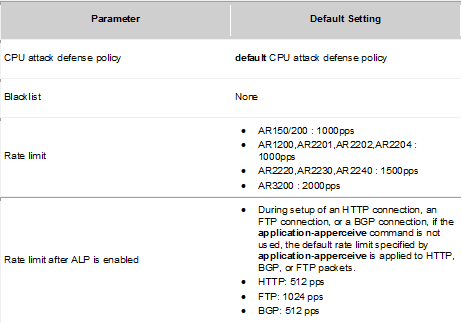
Huawei AR1200 supports the following NAT features: static NAT, port address translation (PAT), internal server, NAT Application Level Gateway (ALG), NAT filtering, NAT mapping, Easy IP, twice NAT, and NAT multi-instance.

  • Static NAT

The number of private addresses is equal to the number of public addresses, so it does not save pull of public addresses.

  • PAT

Maps a public address to multiple private addresses.

  • Internal Server

Hosts in the public network can access an internal server.

  • Easy IP

Takes a public IP address of the interface as the source address after NAT is performed.

  • Twice NAT

Translates both the source and destination addresses. Using in the scenario where IP addresses of hosts on private and public networks overlap.

  • NAT multi-instance

Allows users on private networks to access the public network and allows users in different VPNs to access the public network through the same egress. In addition, users in the VPNs with the same IP address can access the public network. Supports association between VPNs and NAT server, and allows users on the public network to access hosts in the VPNs. This function is applicable when IP addresses of multiple VPNs overlap.

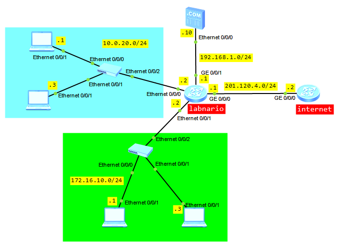
Let’s try to configure NAT based on the below topology:

  1. Users from LAN 10.0.20.0/24 can access internet using a pull of public addresses.
  2. Users from LAN 172.16.10.0/24 can access internet using a public IP of WAN interface.
  3. Users from internet can access internal FTP server 192.168.1.10.

Configure IP addresses and default routing based on the above topology:

labnario
#
interface Vlanif100
 ip address 10.0.20.2 255.255.255.0
#
interface Vlanif200
 ip address 172.16.10.2 255.255.255.0
#
interface Ethernet0/0/0
 portswitch
 port link-type access
 port default vlan 100
#
interface Ethernet0/0/1
 portswitch
 port link-type access
 port default vlan 200
#
interface GigabitEthernet0/0/0
 ip address 201.120.4.1 255.255.255.0
#
interface GigabitEthernet0/0/1
 ip address 192.168.1.1 255.255.255.0
#
ip route-static 0.0.0.0 0.0.0.0 201.120.4.2

internet
#
interface GigabitEthernet0/0/0
 ip address 201.120.4.2 255.255.255.0

Configure outbound NAT on labnario router for hosts in both LANs:

[labnario]acl number 2000
[labnario-acl-basic-2000] rule 5 permit source 10.0.20.0 0.0.0.255

[labnario]acl number 2500
[labnario-acl-basic-2500] rule 5 permit source 172.16.10.0 0.0.0.255

[labnario]nat address-group 1 201.120.4.100 201.120.4.110

[labnario]interface GigabitEthernet 0/0/0
[labnario-GigabitEthernet0/0/0]nat outbound 2000 address-group 1 no-pat
[labnario-GigabitEthernet0/0/0]nat outbound 2500
[labnario-GigabitEthernet0/0/0]display this
#
interface GigabitEthernet0/0/0
 ip address 201.120.4.1 255.255.255.0
 nat outbound 2000 address-group 1 no-pat 
 nat outbound 2500

No-pat indicates one-to-one NAT, that is, only the IP address is translated and the port number is not translated.

Configure NAT server on labnario router to let external users to have FTP access to internal FTP server:

[labnario-GigabitEthernet0/0/0]nat server protocol tcp global 201.120.4.10 ftp inside 192.16.1.10 ftp

Enable the NAT ALG function for FTP packets:

[labnario]nat alg ftp enable

[labnario]display nat alg 

NAT Application Level Gateway Information:
----------------------------------
  Application            Status
----------------------------------
  dns                    Disabled
  ftp                    Enabled
  rtsp                   Disabled
  sip                    Disabled
----------------------------------

After the NAT ALG function is enabled for an application protocol, packets of the application protocol can traverse the NAT server. The application protocol cannot work without the NAT ALG function.

Let’s check if our NAT is configured properly:

[labnario]display nat outbound 
 NAT Outbound Information:
 --------------------------------------------------------------------------
 Interface                     Acl     Address-group/IP/Interface      Type
 --------------------------------------------------------------------------
 GigabitEthernet0/0/0         2000                              1    no-pat
 GigabitEthernet0/0/0         2500                    201.120.4.1    easyip
 --------------------------------------------------------------------------
  Total : 2

[labnario]dis nat server

  Nat Server Information:
  Interface  : GigabitEthernet0/0/0
    Global IP/Port     : 201.120.4.10/21(ftp)
   Inside IP/Port     : 192.16.1.10/21(ftp)
    Protocol : 6(tcp)   
    VPN instance-name  : ----                            
    Acl number         : ----
    Description : ----

  Total :    1

Unfortunately, even NAT commands are supported by eNSP simulator, it does not mean that NAT is supported as a whole. Internal hosts cannot communicate with internet and internal FTP server is not available for public users as well. But this is what I wanted to show you. You can check this NAT configuration on real devices. It should work properly.

Read More »

local attack defense on Huawei AR routers

Let’s assume that a large number of packets are sent to CPU of a device. What will happen if most of these packets are malicious attack packets? CPU usage will become high, what can bring to services’ deterioration. In extreme cases it can lead the device to reboot. We can minimize an impact of the attack on network services, providing the local attack defense function. When such attack occurs, this function ensures non-stop service transmission.

Attack Defense Policy Supported by AR routers:

CPU attack defense:
  • The device uses blacklists to filters invalid packets sent to the CPU
  • The device limits the rate of packets sent to the CPU based on the protocol type
  • The device schedules packets sent to the CPU based on priorities of protocol packets
  • The device uniformly limits the rate of packets with the same priority sent to the CPU and randomly discards the excess packets to protect the CPU
  • ALP is enabled to protect HTTP, FTP and BGP sessions. Packets matching characteristics of the sessions are sent at a high rate, that’s why session-related services are ensured.

Attack source tracing:
  • Attack source tracing checks attack packets sent to the CPU and notifies the administrator by sending logs or alarms so that the administrator can take measures to defend against attacks.

Although each device has the defult configuration of local attack defense policy, you can change it every time you need.

Based on AR documentation:

Default configuration of attack source tracing:

Default configuration of CPU attack defense:

Configuring attack source tracing:

Creating an attack defense policy:

cpu-defend policy policy-name (max 19 attack defense policies including the defualt)

Configuring the threshold for attack source tracing:

auto-defend enable
auto-defend threshold threshold-value

Configuring the alarm function for attack source tracing:

auto-defend alarm enable
auto-defend alarm threshold threshold-value
Configuring CPU Attack Defense:

Configuring a blacklist:

blacklist blacklist-id acl acl-number (how to configure ACL)

Configuring the rate limit for packets sent to the CPU:

packet-type packet-type rate-limit rate-value (excess packets are discarded)

deny packet-type packet-type (discards all packets)

Setting the priority for packets of a specified protocol:

packet-type packet-type priority priority-level

Configuring ALP:

application-apperceive packet-type { bgp | ftp | http } rate-limit rate-value

Configuring the rate limit for all packets sent to the CPU:

rate-limit all-packets pps pps-value

Applying the attack defense policy:

cpu-defend-policy policy-name [ global | slot slot-id ]

[AR3200]cpu-defend-policy labnario (apply the CPU attack defense policy to the SRU)

[AR3200]cpu-defend-policy labnario global (apply the CPU attack defense policy to the LPU)

[AR3200]cpu-defend-policy labnario slot  2 (apply the CPU attack defense policy to slot 2)

Useful maintenace commands:

  • display auto-defend attack-source
  • display auto-defend configuration
  • display cpu-defend policy
  • display cpu-defend policy
  • display cpu-defend statistics
  • display cpu-defend configuration.

Read More »

equivalent of Cisco Private Vlan —> Huawei MUX Vlan

Do you know the Private VLAN feature from Cisco switches? The same feature exists on Huawei switches and is called the MUX VLAN.

How does this feature work?

MUX VLAN allows isolating Layer2 traffic of different interfaces in the same VLAN, and still allowing access to common resources.

Look at the topology below. Let’s assume that we want to configure our labnariosw switch, so that:

  • hosts in VLAN10 should be able to ping each other and ping server in VLAN30
  • hosts in VLAN20 should be able to ping server in VLAN30 but not each other
  • hosts in VLAN10 should not be able to ping hosts in VLAN20.

To do so, we need to define:

  • VLAN30 as a “principal VLAN” and add interface connecting server to this VLAN
  • VLAN10 as a “seprate VLAN” and add user interfaces to it
  • VLAN20 as a “group VLAN” and add user interfaces to this VLAN.

Let’s start configuring our topology. As the first step VLANs 10, 20 and 30 should be configured:

<labnariosw>sys
Enter system view, return user view with Ctrl+Z.
[labnariosw]vlan batch 10 20 30
Info: This operation may take a few seconds. Please wait for a moment...done.

VLAN30 should be defined as a principal, VLAN 10 as a group VLAN, and 20 as a separate VLAN:

[labnariosw]vlan 30
[labnariosw-vlan30]mux-vlan
[labnariosw-vlan30]subordinate group 10
[labnariosw-vlan30]subordinate separate 20

As the last step, switch ports have to be added to the appropriate VLAN and MUX VLAN feature have to be enabled as follows:

[labnariosw]interface Ethernet0/0/1	
[labnariosw-Ethernet0/0/1]port link-type access
[labnariosw-Ethernet0/0/1]port default vlan 10
[labnariosw-Ethernet0/0/1]port mux-vlan enable
[labnariosw]interface Ethernet0/0/2
[labnariosw-Ethernet0/0/1]port link-type access
[labnariosw-Ethernet0/0/1]port default vlan 10
[labnariosw-Ethernet0/0/1]port mux-vlan enable
[labnariosw]interface Ethernet0/0/3
[labnariosw-Ethernet0/0/1]port link-type access
[labnariosw-Ethernet0/0/1]port default vlan 20
[labnariosw-Ethernet0/0/1]port mux-vlan enable
[labnariosw]interface Ethernet0/0/4
[labnariosw-Ethernet0/0/1]port link-type access
[labnariosw-Ethernet0/0/1]port default vlan 20
[labnariosw-Ethernet0/0/1]port mux-vlan enable
[labnariosw]interface Ethernet0/0/5	
[labnariosw-Ethernet0/0/1]port link-type access
[labnariosw-Ethernet0/0/1]port default vlan 30
[labnariosw-Ethernet0/0/1]port mux-vlan enable

That’s all. Some verification commands:

[labnariosw]display vlan 
The total number of vlans is : 4
--------------------------------------------------------------------------------

U: Up;         D: Down;         TG: Tagged;         UT: Untagged;
MP: Vlan-mapping;               ST: Vlan-stacking;
#: ProtocolTransparent-vlan;    *: Management-vlan;
--------------------------------------------------------------------------------

VID  Type    Ports                
--------------------------------------------------------------------------------
1    common  UT:Eth0/0/6(D)     Eth0/0/7(D)     Eth0/0/8(D)     Eth0/0/9(D)     
                Eth0/0/10(D)    Eth0/0/11(D)    Eth0/0/12(D)    Eth0/0/13(D)    
                Eth0/0/14(D)    Eth0/0/15(D)    Eth0/0/16(D)    Eth0/0/17(D)    
                Eth0/0/18(D)    Eth0/0/19(D)    Eth0/0/20(D)    Eth0/0/21(D)    
                Eth0/0/22(D)    GE0/0/1(D)      GE0/0/2(D)                      
10   mux-sub UT:Eth0/0/1(U)     Eth0/0/2(U)                                   
20   mux-sub UT:Eth0/0/3(U)     Eth0/0/4(U)                                     
30   mux     UT:Eth0/0/5(U)           

VID  Status  Property      MAC-LRN Statistics Description      
--------------------------------------------------------------------------------
1    enable  default       enable  disable    VLAN 0001                         
10   enable  default       enable  disable    VLAN 0010                         
20   enable  default       enable  disable    VLAN 0020                         
30   enable  default       enable  disable    VLAN 0030

[labnariosw]display mux-vlan 
Principal Subordinate Type         Interface  
-----------------------------------------------------------------------------
30        -           principal    Ethernet0/0/5
30        20          separate     Ethernet0/0/3 Ethernet0/0/4
30        10          group        Ethernet0/0/1 Ethernet0/0/2
-----------------------------------------------------------------------------

Now the ping test can be done to verify if our MUX VLAN configuration is working (do not forget to address your PCs).

Hosts in VLAN10 should be able to ping each other and ping server in VLAN30:

PC1>ping 192.168.100.2

Ping 192.168.100.2: 32 data bytes, Press Ctrl_C to break
From 192.168.100.2: bytes=32 seq=1 ttl=128 time=15 ms
From 192.168.100.2: bytes=32 seq=2 ttl=128 time=32 ms
From 192.168.100.2: bytes=32 seq=3 ttl=128 time=47 ms
…

PC1>ping 192.168.100.100

Ping 192.168.100.100: 32 data bytes, Press Ctrl_C to break
From 192.168.100.100: bytes=32 seq=1 ttl=128 time=15 ms
From 192.168.100.100: bytes=32 seq=2 ttl=128 time=30 ms
From 192.168.100.100: bytes=32 seq=3 ttl=128 time=16 ms
…

Hosts in VLAN20 should be able to ping server in VLAN30 but not be able to ping each other.

PC3>ping 192.168.100.100

Ping 192.168.100.100: 32 data bytes, Press Ctrl_C to break
From 192.168.100.100: bytes=32 seq=1 ttl=128 time=43 ms
From 192.168.100.100: bytes=32 seq=2 ttl=128 time=46 ms
From 192.168.100.100: bytes=32 seq=3 ttl=128 time=15 ms
…

PC4>ping 192.168.100.100

Ping 192.168.100.100: 32 data bytes, Press Ctrl_C to break
From 192.168.100.100: bytes=32 seq=1 ttl=128 time=43 ms
From 192.168.100.100: bytes=32 seq=2 ttl=128 time=46 ms
From 192.168.100.100: bytes=32 seq=3 ttl=128 time=15 ms
…

PC3>ping 192.168.100.4
Ping 192.168.100.4: 32 data bytes, Press Ctrl_C to break
    Request time out
    Request time out
    Request time out
…

Hosts in VLAN10 should not be able to ping hosts in VLAN20.

PC1>ping 192.168.100.3
Ping 192.168.100.3: 32 data bytes, Press Ctrl_C to break
    Request time out
    Request time out
    Request time out
…

PC1>ping 192.168.100.4
Ping 192.168.100.4: 32 data bytes, Press Ctrl_C to break
    Request time out
    Request time out
    Request time out
…

PC2>ping 192.168.100.3
Ping 192.168.100.3: 32 data bytes, Press Ctrl_C to break
    Request time out
    Request time out
    Request time out
…

PC2>ping 192.168.100.4
Ping 192.168.100.4: 32 data bytes, Press Ctrl_C to break
    Request time out
    Request time out
    Request time out
…

Read More »

how to find TC packets source on Huawei switch

Topology Change (TC) packets are sent when MSTP-enabled interface in a network flaps. If a physical interface frequently alternates between Up and Down, the MSTP status of the device in the network becomes unsteady. As a result, a large number of TC messages are generated, ARP entries are frequently deleted and services are interrupted.

How to find the source of TC packets?

Let’s look at the log, generated on one of the switches in a network. Let’s take Huawei S9300 switch as an example:

Dec 19 2012 11:32:56+10:00 S9300 %%01MSTP/6/RECEIVE_MSTITC(l)[40922]:MSTP received BPDU with TC, MSTP process 0 instance 0, port name is GigabitEthernet6/0/0.

What can we find in this log?

The most important for us is the port number on which the switch received TC packet, in this case interface GE6/0/0. To troubleshoot this problem we have to go to the next switch, connected to interface GE6/0/0 and check logs of that switch. If the neighbouring switch receives TC packets as well, we have to do further troubleshooting. If we find in the logs that MSTP-enabled interface is flapping, we can consider that this interface is the source of the TC packet. If this interface is still flapping, just make it down, to avoid unsteady behaviour.

To check whether the device has received TC messages:

[S9300] display stp 
-------[CIST Global Info][Mode MSTP]-------
CIST Bridge         :57344.00e0-fc00-1597
Bridge Times        :Hello 2s MaxAge 20s FwDly 15s MaxHop 20
CIST Root/ERPC      :0    .0018-826f-fc7a / 20000
CIST RegRoot/IRPC   :57344.00e0-fc00-1597 / 0
CIST RootPortId     :128.2
BPDU-Protection     :disabled
TC or TCN received  :0
TC count per hello  :0
STP Converge Mode   :Nomal
Time since last TC :2 days 14h:16m:15s    

-------[MSTI 1 Global Info]-------
MSTI Bridge ID      :4096.00e0-fc00-1597
MSTI RegRoot/IRPC   :4096.00e0-fc00-1597 / 0
MSTI RootPortId     :0.0
Master Bridge       :57344.00e0-fc00-1597
Cost to Master      :0
TC received         :0
TC count per hello  :2

If a switch receives lots of TC packets, please run the following hidden command several times to check and compare which ports receive a large number of TC packets:

[S9300]_h (enter into hidden mode)
[S9300-hidecmd]display stp tc (in V1R3 software version)
 ---------- Stp Instance 0 tc or tcn count ----------
 Port GigabitEthernet3/0/0    0
 Port GigabitEthernet3/0/1    4
 Port GigabitEthernet4/0/2    2
 Port GigabitEthernet4/0/3    0
 Port GigabitEthernet6/0/0    8
 Port GigabitEthernet6/0/1    0

[S9300-hidecmd]display stp tc-bpdu statistics (in V1R6 software version)
 -------------------------- STP TC/TCN information --------------------------
 MSTID Port                        TC(Send/Receive)      TCN(Send/Receive)
 0     GigabitEthernet3/0/0        12/1                  0/0
 0     GigabitEthernet3/0/1        1/0                   0/0
 0     GigabitEthernet4/0/2        4/7                   0/0
 0     GigabitEthernet4/0/3        2/0                   0/0
 0     GigabitEthernet6/0/0        0/10                  0/0
 0     GigabitEthernet6/0/1        0/6                   0/0

We can reset these statistics using the following command:

<S9303>reset stp statistics

Read More »