Some time ago we talked about a basic configuration of BGP/MPLS VPNs. Let’s go on with hub&spoke networking today. Such solution can be adopted to control the mutual access of users, when an access control device is set. In this case no direct route exists between spoke sites. A spoke site advertises routes to a hub site and then the hub site advertises the routes to other spoke sites. Thus, communication between spoke sites is controlled by hub site.
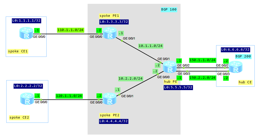
Let’s look at our topology:
Configuration roadmap:
- Configure IP addresses (omitted here).
- Configure IGP protocol between PE routers (omitted here).
- Configure MPLS and LDP on PE routers (omitted here).
- Configure MP-BGP relationship between spoke PEs and hub PE (omitted here).
- Create VPN instance on spoke PEs and set different vpn-targets for export and import.
- Create two VPN instances on hub PE.
- Configure static routes between spoke PEs and spoke CEs.
- Configure EBGP between hub PE and hub CE (the hub PE must be configured to permit the existence of repeated local AS numbers).
Create VPN instance on spoke PEs:
spoke_PE1
#
ip vpn-instance labnario
 ipv4-family
  route-distinguisher 500:1
  vpn-target 200:1 export-extcommunity
  vpn-target 300:1 import-extcommunity
#
interface GigabitEthernet0/0/0
 ip binding vpn-instance labnario
 ip address 110.1.1.2 255.255.255.0

spoke_PE2
#
ip vpn-instance labnario
 ipv4-family
  route-distinguisher 500:2
  vpn-target 300:1 200:1 export-extcommunity
  vpn-target 200:1 300:1 import-extcommunity
#
interface GigabitEthernet0/0/0
 ip binding vpn-instance labnario
 ip address 120.1.1.2 255.255.255.0
Create VPN instances on hub PE:
#
ip vpn-instance labnario_in
 ipv4-family
  route-distinguisher 500:500
  vpn-target 200:1 import-extcommunity
#
ip vpn-instance labnario_out
 ipv4-family
  route-distinguisher 500:510
  vpn-target 300:1 export-extcommunity
#
interface GigabitEthernet0/0/2
 ip binding vpn-instance labnario_in
 ip address 150.1.1.1 255.255.255.0
#
interface GigabitEthernet0/0/3
 ip binding vpn-instance labnario_out
 ip address 150.2.2.1 255.255.255.0
The configuration of a VPN target on a PEs must comply with the following rules:
- The export target of spoke PE must be equal to the import target of hub PE. The import target of spoke PE must be equal to the export target of hub PE. The import route target of a spoke PE is different from the export route targets of other spoke PEs.
- A hub PE requires two interfaces or sub-interfaces. One for receiving routes from spoke PEs, and the import target of the VPN instance on the interface is spoke. The other advertises the routes to spoke PEs, and the export target of the VPN instance on the interface is hub.
Configure static routes between spoke PEs and spoke CEs:
[spoke_PE1]ip route-static vpn-instance labnario 1.1.1.1 255.255.255.255 110.1.1.1
[spoke_PE2]ip route-static vpn-instance labnario 2.2.2.2 255.255.255.255 120.1.1.1
Configure EBGP between hub PE and hub CE:
hub_PE
#
ipv4-family vpn-instance labnario_in
  import-route direct
  peer 150.1.1.2 as-number 200
 #
 ipv4-family vpn-instance labnario_out
  import-route direct
  peer 150.2.2.2 as-number 200
  peer 150.2.2.2 allow-as-loop

hub_CE
#
bgp 200
 peer 150.1.1.1 as-number 100
 peer 150.2.2.1 as-number 100
 #
 ipv4-family unicast
  undo synchronization
  import-route direct
  peer 150.1.1.1 enable
  peer 150.2.2.1 enable
If EBGP runs between a hub PE and a hub CE, the hub PE performs the AS-Loop detection on the route. If the hub PE detects its own AS number in the route, it discards the route. In this case, to implement the hub&spoke networking, the hub PE must be configured to permit the existence of repeated local AS numbers. We don’t have such situation in case of IGB connection between hub PE and hub CE.
Let’s look how it works.
Check communication between spoke PEs (use Ping and tracert command):
[spoke_CE1]ping 2.2.2.2
  PING 2.2.2.2: 56  data bytes, press CTRL_C to break
    Reply from 2.2.2.2: bytes=56 Sequence=1 ttl=250 time=390 ms
    Reply from 2.2.2.2: bytes=56 Sequence=2 ttl=250 time=170 ms
    Reply from 2.2.2.2: bytes=56 Sequence=3 ttl=250 time=120 ms
    Reply from 2.2.2.2: bytes=56 Sequence=4 ttl=250 time=180 ms
    Reply from 2.2.2.2: bytes=56 Sequence=5 ttl=250 time=160 ms

  --- 2.2.2.2 ping statistics ---
    5 packet(s) transmitted
    5 packet(s) received
    0.00% packet loss
    round-trip min/avg/max = 120/204/390 ms

[spoke_CE1]tracert 2.2.2.2
 traceroute to  2.2.2.2(2.2.2.2), max hops: 30 ,packet length: 40,press CTRL_C to break
 1 110.1.1.2 130 ms  40 ms  70 ms
 2 150.2.2.1 90 ms  60 ms  80 ms
 3 150.2.2.2 90 ms  80 ms  80 ms
 4 150.1.1.1 90 ms  80 ms  80 ms
 5 120.1.1.2 110 ms  120 ms  130 ms
 6 120.1.1.1 170 ms  220 ms  140 ms

[spoke_CE2]ping 1.1.1.1
  PING 1.1.1.1: 56  data bytes, press CTRL_C to break
    Reply from 1.1.1.1: bytes=56 Sequence=1 ttl=250 time=170 ms
    Reply from 1.1.1.1: bytes=56 Sequence=2 ttl=250 time=180 ms
    Reply from 1.1.1.1: bytes=56 Sequence=3 ttl=250 time=140 ms
    Reply from 1.1.1.1: bytes=56 Sequence=4 ttl=250 time=190 ms
    Reply from 1.1.1.1: bytes=56 Sequence=5 ttl=250 time=130 ms

  --- 1.1.1.1 ping statistics ---
    5 packet(s) transmitted
    5 packet(s) received
    0.00% packet loss
    round-trip min/avg/max = 130/162/190 ms

[spoke_CE2]tracert 1.1.1.1
 traceroute to  1.1.1.1(1.1.1.1), max hops: 30 ,packet length: 40,press CTRL_C to break
 1 120.1.1.2 70 ms  40 ms  50 ms
 2 150.2.2.1 80 ms  110 ms  70 ms
 3 150.2.2.2 100 ms  110 ms  90 ms
 4 150.1.1.1 80 ms  80 ms  110 ms
 5 110.1.1.2 140 ms  150 ms  130 ms
 6 110.1.1.1 170 ms  170 ms  170 ms
Display routing for each VPN instance on hub PE:
[hub_PE]dis ip rout vpn-instance labnario_in
Route Flags: R - relay, D - download to fib
------------------------------------------------------------------------------
Routing Tables: labnario_in
         Destinations : 8        Routes : 8

Destination/Mask    Proto   Pre  Cost      Flags NextHop         Interface

        1.1.1.1/32  IBGP    255  0          RD   3.3.3.3         GigabitEthernet0/0/1
        2.2.2.2/32  IBGP    255  0          RD   4.4.4.4         GigabitEthernet0/0/0
        6.6.6.6/32  EBGP    255  0           D   150.1.1.2       GigabitEthernet0/0/2
      110.1.1.0/24  IBGP    255  0          RD   3.3.3.3         GigabitEthernet0/0/1
      120.1.1.0/24  IBGP    255  0          RD   4.4.4.4         GigabitEthernet0/0/0
      150.1.1.0/24  Direct  0    0           D   150.1.1.1       GigabitEthernet0/0/2
      150.1.1.1/32  Direct  0    0           D   127.0.0.1       GigabitEthernet0/0/2
      150.2.2.0/24  EBGP    255  0           D   150.1.1.2       GigabitEthernet0/0/2

[hub_PE]dis ip rout vpn-instance labnario_out
Route Flags: R - relay, D - download to fib
------------------------------------------------------------------------------
Routing Tables: labnario_out
         Destinations : 8        Routes : 8

Destination/Mask    Proto   Pre  Cost      Flags NextHop         Interface

        1.1.1.1/32  EBGP    255  0           D   150.2.2.2       GigabitEthernet0/0/3
        2.2.2.2/32  EBGP    255  0           D   150.2.2.2       GigabitEthernet0/0/3
        6.6.6.6/32  EBGP    255  0           D   150.2.2.2       GigabitEthernet0/0/3
      110.1.1.0/24  EBGP    255  0           D   150.2.2.2       GigabitEthernet0/0/3
      120.1.1.0/24  EBGP    255  0           D   150.2.2.2       GigabitEthernet0/0/3
      150.1.1.0/24  EBGP    255  0           D   150.2.2.2       GigabitEthernet0/0/3
      150.2.2.0/24  Direct  0    0           D   150.2.2.1       GigabitEthernet0/0/3
      150.2.2.1/32  Direct  0    0           D   127.0.0.1       GigabitEthernet0/0/3
Comparing these outputs we can notice that the routing information, advertised by a spoke CE, is forwarded to the hub CE and hub PE, before being transmitted to other spoke PEs.
Read More »