Layer 2 tunneling protocol (L2TP) connection can be established in the following tree modes:
- NAS-initializated
- Client-initializated
- LAC-auto-initializated.
This is not my job to tell you about the theory. You can find plenty of information about L2TP on the internet. Let’s focus today on the third mode.
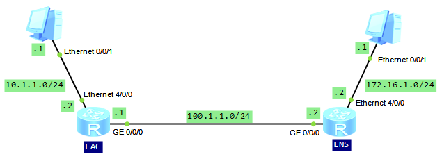
In most cases, an L2TP user directly dials up to a LAC, and only PPP connection is established between the user and LAC. Unlike NAS and Client-initializated modes, in LAC-auto-initializated mode users can connect to the LAC by sending IP packets. At the same time LAC needs to have a PPP user created and a tunnel with the LNS established. The two ends of an L2TP tunnel reside on LAC and LNS respectively. As you can see from the topology below, in LAC-auto-initiated mode, LAN can be directly connected to LAC.
Let’s look how to configure L2TP on Huawei routers.
Configure IP addresses for the user-side and public-network-side interfaces on LAC and LNS:
LAC
#
interface Ethernet4/0/0
 ip address 10.1.1.2 255.255.255.0
#
interface GigabitEthernet0/0/0
 ip address 100.1.1.1 255.255.255.0

LNS
#
interface Ethernet4/0/0
 ip address 172.16.1.2 255.255.255.0
#
interface GigabitEthernet0/0/0
 ip address 100.1.1.2 255.255.255.0
Enable L2TP globally on LAC and configure parameters of L2TP group to establish an L2TP connection to LNS:
[LAC]l2tp enable
[LAC]l2tp-group 1
[LAC-l2tp1]tunnel name lac
[LAC-l2tp1]tunnel password simple  labnario
[LAC-l2tp1]start l2tp ip 100.1.1.2 fullusername labnario
Configure authentication mode, user name and password for virtual-template interface. IP address will be negotiated:
[LAC]interface Virtual-Template 1
[LAC-Virtual-Template1]ppp authentication-mode chap
[LAC-Virtual-Template1] ppp chap user labnario
[LAC-Virtual-Template1] ppp chap password simple labnario
[LAC-Virtual-Template1] ip address ppp-negotiate
Enable LAC to dial up and establish an L2TP tunnel:
[LAC-Virtual-Template1]l2tp-auto-client enable
Configure a static route so that packets sent to 172.16.1.0 are forwarded through L2TP tunnel:
[LAC]ip route-static 172.16.1.0 255.255.255.0 Virtual-Template1
Configure AAA on the LNS:
[LNS]display current-configuration configuration aaa
#
aaa
 local-user labnario password cipher %$%$9\1U#=BaE-BjypW#.c8!8I$K%$%$
 local-user labnario service-type ppp
Configure an IP address pool to allocate an IP address to the dial-up interface of the LAC:
[LNS]ip pool 1
[LNS-ip-pool-1]gateway-list 192.168.1.1
[LNS-ip-pool-1] network 192.168.1.0 mask 255.255.255.0
Create a virtual interface template and configure PPP negotiation parameters:
[LNS]interface Virtual-Template1
[LNS-Virtual-Template1] ppp authentication-mode chap
[LNS-Virtual-Template1] remote address pool 1
[LNS-Virtual-Template1] ip address 192.168.1.1 255.255.255.0
Enable L2TP and configure parameters for an L2TP group:
[LNS]l2tp enable
[LNS]l2tp-group 1
[LNS-l2tp1]allow l2tp virtual-template 1 remote lac
[LNS-l2tp1] tunnel password simple  labnario
[LNS-l2tp1] tunnel name lns
Configure a static route so that packets sent to 10.1.1.0 are forwarded through L2TP tunnel:
[LNS]ip route-static 10.1.1.0 255.255.255.0 Virtual-Template1
Verify if L2TP session was established properly:
[LAC]dis l2tp session

 LocalSID  RemoteSID  LocalTID
  1         1          1

 Total session = 1

[LAC]dis l2tp tunnel

 Total tunnel = 1
 LocalTID RemoteTID RemoteAddress    Port   Sessions RemoteName
 1        1         100.1.1.2        42246  1        lns
Check communication between PCs:
PC>ping 172.16.1.1

Ping 172.16.1.1: 32 data bytes, Press Ctrl_C to break
From 172.16.1.1: bytes=32 seq=1 ttl=126 time=16 ms
From 172.16.1.1: bytes=32 seq=2 ttl=126 time=15 ms
From 172.16.1.1: bytes=32 seq=3 ttl=126 time=15 ms
From 172.16.1.1: bytes=32 seq=4 ttl=126 time=16 ms
From 172.16.1.1: bytes=32 seq=5 ttl=126 time<1 ms

--- 172.16.1.1 ping statistics ---
  5 packet(s) transmitted
  5 packet(s) received
  0.00% packet loss
  round-trip min/avg/max = 0/12/16 ms
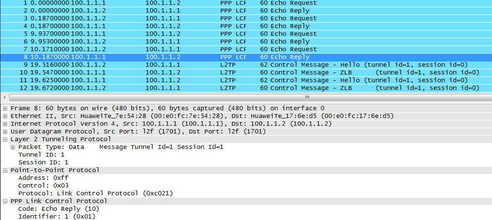
Let’s catch packets on the link between LAC and LNS:
 Labnario Huawei From Scratch

