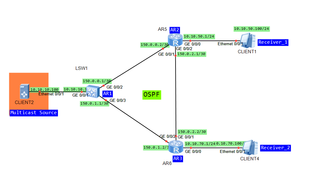
I wanted to use AR routers to prepare PIM SM lab but it turned out that there is a problem with cooperation between multicast source and AR router. Of course I am talking about network simulator eNSP. Finally I decided to use eNSP with S5700. So we have topology like in the last two posts:
- Configure VLANs, VLAN interfaces and IP addresses based on the topology (omitted).
- Configure OSPF to ensure connectivity between switches (omitted).
- Enable multicast on both switches.
- Enable PIM SM on all interfaces.
- Enable IGMP on receivers’ interfaces.
- Set static RP for both switches (Loopback0 of SwitchB).
- Address of multicast group G: 225.1.1.1.
- Address of multicast group S: 10.10.10.100.
Display IP routing tables of both switches:
[SwitchA]dis ip routing-table
Route Flags: R - relay, D - download to fib
------------------------------------------------------------------------------
Routing Tables: Public
         Destinations : 9        Routes : 9

Destination/Mask    Proto   Pre  Cost      Flags NextHop         Interface

        1.1.1.1/32  OSPF    10   1           D   150.1.1.1       Vlanif300
     10.10.10.0/24  OSPF    10   2           D   150.1.1.1       Vlanif300
     10.10.20.0/24  OSPF    10   2           D   150.1.1.1       Vlanif300
     10.10.30.0/24  Direct  0    0           D   10.10.30.1      Vlanif400
     10.10.30.1/32  Direct  0    0           D   127.0.0.1       Vlanif400
      127.0.0.0/8   Direct  0    0           D   127.0.0.1       InLoopBack0
      127.0.0.1/32  Direct  0    0           D   127.0.0.1       InLoopBack0
      150.1.1.0/30  Direct  0    0           D   150.1.1.2       Vlanif300
      150.1.1.2/32  Direct  0    0           D   127.0.0.1       Vlanif300

[SwitchB]dis ip routing-table
Route Flags: R - relay, D - download to fib
------------------------------------------------------------------------------
Routing Tables: Public
         Destinations : 10       Routes : 10

Destination/Mask    Proto   Pre  Cost      Flags NextHop         Interface

        1.1.1.1/32  Direct  0    0           D   127.0.0.1       LoopBack0
     10.10.10.0/24  Direct  0    0           D   10.10.10.1      Vlanif100
     10.10.10.1/32  Direct  0    0           D   127.0.0.1       Vlanif100
     10.10.20.0/24  Direct  0    0           D   10.10.20.1      Vlanif200
     10.10.20.1/32  Direct  0    0           D   127.0.0.1       Vlanif200
     10.10.30.0/24  OSPF    10   2           D   150.1.1.2       Vlanif300
      127.0.0.0/8   Direct  0    0           D   127.0.0.1       InLoopBack0
      127.0.0.1/32  Direct  0    0           D   127.0.0.1       InLoopBack0
      150.1.1.0/30  Direct  0    0           D   150.1.1.1       Vlanif300
      150.1.1.1/32  Direct  0    0           D   127.0.0.1       Vlanif300
Enable multicast on both switches:
[SwitchA]multicast routing-enable
[SwitchB]multicast routing-enable
Enable PIM SM on all interfaces and IGMP on receivers’ interfaces:
[SwitchA]dis cur int Vlanif
#
interface Vlanif300
 ip address 150.1.1.2 255.255.255.252
 pim sm
#
interface Vlanif400
 ip address 10.10.30.1 255.255.255.0
 pim sm
 igmp enable
#

[SwitchB]dis cur interface Vlanif
#
interface Vlanif100
 ip address 10.10.10.1 255.255.255.0
 pim sm
#
interface Vlanif200
 ip address 10.10.20.1 255.255.255.0
 pim sm
 igmp enable
#
interface Vlanif300
 ip address 150.1.1.1 255.255.255.252
 pim sm
#
Verify PIM and IGMP (SwitchA as an example):
[SwitchA]dis pim neighbor
 VPN-Instance: public net
 Total Number of Neighbors = 1

 Neighbor        Interface           Uptime   Expires  Dr-Priority  BFD-Session
 150.1.1.1       Vlanif300           00:07:44 00:01:31 1            N

[SwitchA]display pim interface
 VPN-Instance: public net
 Interface           State NbrCnt HelloInt   DR-Pri     DR-Address
 Vlanif300           up    1      30         1          150.1.1.2       (local)
 Vlanif400           up    0      30         1          10.10.30.1      (local)

[SwitchA]dis igmp interface
Interface information
 Vlanif400(10.10.30.1):
   IGMP is enabled
   Current IGMP version is 2
   IGMP state: up
   IGMP group policy: none
   IGMP limit: -
   Value of query interval for IGMP (negotiated): -
   Value of query interval for IGMP (configured): 60 s
   Value of other querier timeout for IGMP: 0 s
   Value of maximum query response time for IGMP: 10 s
   Querier for IGMP: 10.10.30.1 (this router)
Jul 15 2014 10:18:44.880.2-08:00 SwitchA PIM/7/NBR:(public net): PIM ver 2 HEL se
nding 150.1.1.2 -> 224.0.0.13 on Vlanif300  (P012213)
Jul 15 2014 10:18:44.880.3-08:00 SwitchA PIM/7/NBR:(public net): Option: 1, lengt
h: 2 (P012260)
Jul 15 2014 10:18:44.880.4-08:00 SwitchA PIM/7/NBR:(public net): Holdtime: 105 (P
012278)
Jul 15 2014 10:18:44.880.5-08:00 SwitchA PIM/7/NBR:(public net): Option: 19, leng
th: 4 (P012260)
Jul 15 2014 10:18:44.880.6-08:00 SwitchA PIM/7/NBR:(public net): DR priority: 1 (
P012324)
Jul 15 2014 10:18:44.880.7-08:00 SwitchA PIM/7/NBR:(public net): Option: 20, leng
th: 4 (P012260)
Jul 15 2014 10:18:44.880.8-08:00 SwitchA PIM/7/NBR:(public net): GenID: 0X9063A18
A (P012343)
Jul 15 2014 10:18:44.880.9-08:00 SwitchA PIM/7/NBR:(public net): Option: 65004, l
ength: 0 (P012260)
Jul 15 2014 10:18:44.880.10-08:00 SwitchA PIM/7/NBR:(public net): Unknown option
value: (P012462)
Jul 15 2014 10:18:44.880.11-08:00 SwitchA PIM/7/NBR:(public net): Option: 2, leng
th: 4 (P012260)
Jul 15 2014 10:18:44.880.12-08:00 SwitchA PIM/7/NBR:(public net): Tbit: unset  (P
012300)
Jul 15 2014 10:18:44.880.13-08:00 SwitchA PIM/7/NBR:(public net): Lan delay: 500
(P012303)
Jul 15 2014 10:18:44.880.14-08:00 SwitchA PIM/7/NBR:(public net): Override interv
al: 2500 (P012306)
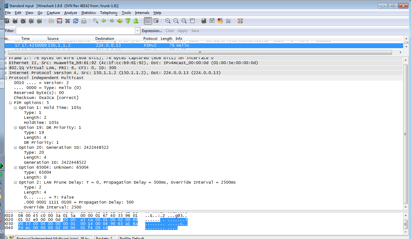
During neighbor discovery process, each PIM device sends Hello messages. Then DR election is performed, based on carrying the DR priority. The PIM device with the highest DR priority wins. If PIM devices have the same DR priority , the PIM device with the highest IP address wins. There are 2 multicast DRs:
- multicast source DR – responsible for sending Register messages to RP (Rendezvous Point)
- multicast receiver DR – responsible for forwarding multicast data to the group members.
Set static RP for both switches:
[SwitchA]pim
[SwitchA-pim]static-rp 1.1.1.1

[SwitchB]pim
[SwitchB-pim]static-rp 1.1.1.1

[SwitchA-pim]display pim rp-info
 VPN-Instance: public net
 PIM SM static RP Number:1
     Static RP: 1.1.1.1
A static RP is recommended on small and mid-sized networks. A dynamic RP can be used on a large-scale network to improve network reliability and maintainability. In dynamic RP, candidate BSRs and RPs must be configured. Elected BSR collects RP information, summarizes that information into an RP-set and advertises the RP-set to the entire PIM-SM network.
When the source sends the first multicast packet to a multicast group G, the source’s DR encapsulates the multicast packet in a Register message and unicasts it to the RP. An (S, G) entry is created on the RP and source information is registered. When a new group member appears on the network, the receiver’s DR on the group member side sends a JOIN message to the RP. A (*, G) entry is created hop by hop and an RPT with the RP as the root is generated.
<SwitchA>dis pim routing-table
 VPN-Instance: public net
 Total 1 (*, G) entry; 1 (S, G) entry

 (*, 225.1.1.1)
     RP: 1.1.1.1
     Protocol: pim-sm, Flag: WC
     UpTime: 00:01:50
     Upstream interface: Vlanif300
         Upstream neighbor: 150.1.1.1
         RPF prime neighbor: 150.1.1.1
     Downstream interface(s) information:
     Total number of downstreams: 1
         1: Vlanif400
             Protocol: igmp, UpTime: 00:01:50, Expires: -

 (10.10.10.100, 225.1.1.1)
     RP: 1.1.1.1
     Protocol: pim-sm, Flag: SPT ACT
     UpTime: 00:05:57
     Upstream interface: Vlanif300
         Upstream neighbor: 150.1.1.1
         RPF prime neighbor: 150.1.1.1
     Downstream interface(s) information:
     Total number of downstreams: 1
         1: Vlanif400
             Protocol: pim-sm, UpTime: 00:01:50, Expires: -
Debugging PIM and IGMP shows how RPT is created:
<SwitchA>
Jul 15 2014 11:02:17.140.1-08:00 SwitchA IGMP/7/REPORT:Received v2 report for gro
up 225.1.1.1 on interface Vlanif400(10.10.30.1) (G082859)
Jul 15 2014 11:02:17.140.2-08:00 SwitchA PIM/7/ROUT:(public net): PIM-SM: Create
(*, 225.1.1.1) entry in mrt. (S0116518)
Jul 15 2014 11:02:17.140.3-08:00 SwitchA PIM/7/ROUT:(public net): PIM-SM: Adding
iif Vlanif300 to (0.0.0.0, 225.1.1.1). (S014449)
Jul 15 2014 11:02:17.140.4-08:00 SwitchA PIM/7/ROUT:(public net): PIM-SM: Add oif
: Vlanif400 (10.10.30.1) for (10.10.10.100, 225.1.1.1) (S0114105)
Jul 15 2014 11:02:17.140.5-08:00 SwitchA PIM/7/ROUT:(public net): PIM-SM: Deletin
g iif 150.1.1.2 from (10.10.10.100, 225.1.1.1). (S013702)
Jul 15 2014 11:02:17.140.6-08:00 SwitchA PIM/7/ROUT:(public net): PIM-SM: Adding
iif 150.1.1.2 to (10.10.10.100, 225.1.1.1). (S014195)
Jul 15 2014 11:02:17.140.7-08:00 SwitchA IGMP/7/EVENT:Creating group(225.1.1.1) f
or interface Vlanif400(10.10.30.1) (G014427)
Jul 15 2014 11:02:17.140.8-08:00 SwitchA IGMP/7/TIMER:Enqueue group(225.1.1.1) on
 interface Vlanif400(10.10.30.1) in group_calq. (G016648)
Jul 15 2014 11:02:17.140.9-08:00 SwitchA PIM/7/JP:(public net): PIM ver 2 JP  sen
ding 150.1.1.2 -> 224.0.0.13 on Vlanif300  (P012933)
Jul 15 2014 11:02:17.140.10-08:00 SwitchA PIM/7/JP:(public net): Upstream 150.1.1
.1, Groups 1, Holdtime 210 (P012939)
Jul 15 2014 11:02:17.140.11-08:00 SwitchA PIM/7/JP:(public net): Group: 225.1.1.1
/32 --- 2 joins 0 prune (P012949)
Jul 15 2014 11:02:17.140.12-08:00 SwitchA PIM/7/JP:(public net): Join: 1.1.1.1/32
 SWR (P012959)
Jul 15 2014 11:02:17.140.13-08:00 SwitchA PIM/7/JP:(public net): Join: 10.10.10.1
00/32 S (P012959)
When a group member and a multicast source that sends multicast data to the group appear on the network, multicast data is encapsulated in a Register message and then unicasted to the RP. The RP then forwards the multicast data along the RPT to group members. As RPT doesn’t have to be a shortest path (SPT), SPT switchover is performed. By default, the RP performs SPT switchover immediately after receiving the first Register message and the receiver’s DR performs SPT switchover immediately after receiving the first multicast packet. Then multicast packets are transmitted based on the SPT.