After long time a new version of Huawei eNSP has been released:

New features:
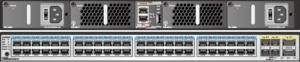
- Support CE6800 DC switch.
- Support any wvrp device.
- Export vrpcfg.cfg from usg5500.
After long time a new version of Huawei eNSP has been released:
New features:
 Huawei AR routers have easy and effective memory usage monitoring tool. When memory usage exceeds configured threshold, the system logs the event and generates an alarm. When memory usage falls within the alarm threshold, the system generates a clear alarm.
By default memory usage threshold is set to 90% when the memory capacity on the interface board is lower than or equal to 128MB, and 95% when the memory capacity is higher that 128MB. Memory usage threshold can be easly changed using command:
[labnario]set memory-usage threshold 75
Well known feature from JunOS, now implemented by Huawei in Cloud Engines switches like CE12800, CE7800, CE6800 and CE5800. This feature will be implemented in NE routers as well, starting from V8R6 software version.
We have opportunity to choose wheter changes can be saved automatically or must wait for administrator’s confirmation:
system-view
In this case, the configuration takes effect after you run the commit command (two-phase validation mode).
system-view immediately
The last article dealt with outbound NAT. Let’s focus today on NAT server. NAT server enables private network servers to provide services for external networks with public IP addresses. In this lab, our enterprise provides FTP services for external users.
We can use the topology from the last post:

In our case AR router works as FTP server:
What does it mean outbound NAT?
Outbound NAT translates the source IP addresses of packets sent from a high-priority security zone to a low-priority one.
I allowed myself to post a flowchart of configuring intranet users to access extranet through NAT (from Huawei documentation):

It easily lets us to choose a suitable way of configuring outbound NAT. In this lab I will try to do a review of these methods.