There are two interface backup modes:
- Active/standby
- Load balancing
In common active/standby mode only one interface transmit services at any time. When active interface works properly, it transmit all the traffic. In case of fault of the primary interface, a backup interface with the highest priority starts transmitting packets. If primary interface recovers, traffic is switched back to active interface.
In load balancing mode, in case traffic volume exceeds an upper threshold set for active interface, a backup interface with the highest priority starts transmitting packets and load balancing is performed.
Which mode we have is determined by upper and lower thresholds. If thresholds are not set, active/standby mode is used. Otherwise, load balancing mode is used.
Let’s assume that we have the following topology:
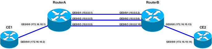
Normally traffic from CE1 router to CE2 router should go through interface GE0/0/1 of RouterA. What we want to do is to configure backup interfaces to ensure that one of them will hand over this traffic in case the active interface is DOWN.
First configure IP addresses and routing between these four routers (below CE1 and RouterA as an example):
CE1 configuration:
#
interface GigabitEthernet0/0/0
 ip address 172.16.10.2 255.255.255.252
#
ip route-static 0.0.0.0 0.0.0.0 172.16.10.1

RouterA configuration:
#
interface GigabitEthernet0/0/0
 ip address 172.16.10.1 255.255.255.252
#
interface GigabitEthernet0/0/1
 undo shutdown
 ip address 10.0.0.1 255.255.255.252
#
interface GigabitEthernet0/0/2
 ip address 10.0.0.5 255.255.255.252
#
interface GigabitEthernet0/0/3
 ip address 10.0.0.9 255.255.255.252
#
ip route-static 172.16.10.12 255.255.255.252 10.0.0.6
ip route-static 172.16.10.12 255.255.255.252 10.0.0.10
ip route-static 172.16.10.12 255.255.255.252 10.0.0.2
Displaying routing table of RouterA we can see that a network 172.16.10.12 is available through these 3 configured static routes:
[RouterA]display ip routing-table
Route Flags: R - relay, D - download to fib
------------------------------------------------------------------------------
Routing Tables: Public
        Destinations : 11       Routes : 13

Destination/Mask    Proto  Pre  Cost       Flags NextHop         Interface

       10.0.0.0/30  Direct 0    0            D   10.0.0.1        GigabitEthernet0/0/1
       10.0.0.1/32  Direct 0    0            D   127.0.0.1       InLoopBack0
       10.0.0.4/30  Direct 0    0            D   10.0.0.5        GigabitEthernet0/0/2
       10.0.0.5/32  Direct 0    0            D   127.0.0.1       InLoopBack0
       10.0.0.8/30  Direct 0    0            D   10.0.0.9        GigabitEthernet0/0/3
       10.0.0.9/32  Direct 0    0            D   127.0.0.1       InLoopBack0
      127.0.0.0/8   Direct 0    0            D   127.0.0.1       InLoopBack0
      127.0.0.1/32  Direct 0    0            D   127.0.0.1       InLoopBack0
    172.16.10.0/30  Direct 0    0            D   172.16.10.1     GigabitEthernet0/0/0
    172.16.10.1/32  Direct 0    0            D   127.0.0.1       InLoopBack0
   172.16.10.12/30  Static 60   0           RD   10.0.0.6        GigabitEthernet0/0/2
                    Static 60   0           RD   10.0.0.10       GigabitEthernet0/0/3
                    Static 60   0           RD   10.0.0.2        GigabitEthernet0/0/1
Now we can configure backup interface on interface GE0/0/1 of RouterA:
#
interface GigabitEthernet0/0/1
 standby interface GigabitEthernet0/0/2 60
 standby interface GigabitEthernet0/0/3 30
#
Look what we can see now. Backup interfaces are in DOWN state. Only active interface is UP:
[RouterA-GigabitEthernet0/0/1]display ip interface brief
*down: administratively down
!down: FIB overload down
(l): loopback
(s): spoofing
The number of interface that is UP in Physical is 3
The number of interface that is DOWN in Physical is 2
The number of interface that is UP in Protocol is 3
The number of interface that is DOWN in Protocol is 2

Interface                         IP Address/Mask      Physical   Protocol
GigabitEthernet0/0/0              172.16.10.1/30       up         up
GigabitEthernet0/0/1              10.0.0.1/30          up         up
GigabitEthernet0/0/2              10.0.0.5/30          down       down
GigabitEthernet0/0/3              10.0.0.9/30          down       down
NULL0                             unassigned           up         up(s)
In IP routing table we have only one static route:
[RouterA]display ip routing-table
Route Flags: R - relay, D - download to fib
------------------------------------------------------------------------------
Routing Tables: Public
        Destinations : 7        Routes : 7

Destination/Mask    Proto  Pre  Cost       Flags NextHop         Interface

       10.0.0.0/30  Direct 0    0            D   10.0.0.1        GigabitEthernet0/0/1
       10.0.0.1/32  Direct 0    0            D   127.0.0.1       InLoopBack0
      127.0.0.0/8   Direct 0    0            D   127.0.0.1       InLoopBack0
      127.0.0.1/32  Direct 0    0            D   127.0.0.1       InLoopBack0
    172.16.10.0/30  Direct 0    0            D   172.16.10.1     GigabitEthernet0/0/0
    172.16.10.1/32  Direct 0    0            D   127.0.0.1       InLoopBack0
   172.16.10.12/30  Static 60   0           RD   10.0.0.2        GigabitEthernet0/0/1
Trace from CE1 to CE2 shows that traffic is going through active interface of RouterA (GE0/0/1):
<CE1>tracert 172.16.10.14
 traceroute to  172.16.10.14(172.16.10.14), max hops: 30 ,packet length: 40
 1 172.16.10.1 30 ms  50 ms  40 ms
 2 10.0.0.2 80 ms  80 ms  50 ms
 3 172.16.10.14 80 ms  90 ms  90 ms
Now we can shutdown interface GE0/0/1 of RouterA:
[RouterA-GigabitEthernet0/0/1]shutdown

[RouterA-GigabitEthernet0/0/1]display this
interface GigabitEthernet0/0/1
 shutdown
 ip address 10.0.0.1 255.255.255.252
 standby interface GigabitEthernet0/0/2 60
 standby interface GigabitEthernet0/0/3 30
Now traffic from CE1 to CE2 is going through GE0/0/2 of RouterA:
<CE>tracert 172.16.10.14
 traceroute to  172.16.10.14(172.16.10.14), max hops: 30 ,packet length: 40
 1 172.16.10.1 30 ms  30 ms  50 ms
 2 10.0.0.6 80 ms  60 ms  50 ms
 3 172.16.10.14 110 ms  100 ms  100 ms
What we can see on RouterA is:
[RouterA]display ip routing-table
Route Flags: R - relay, D - download to fib
------------------------------------------------------------------------------
Routing Tables: Public
        Destinations : 7        Routes : 7

Destination/Mask    Proto  Pre  Cost       Flags NextHop         Interface

       10.0.0.4/30  Direct 0    0            D   10.0.0.5        GigabitEthernet0/0/2
       10.0.0.5/32  Direct 0    0            D   127.0.0.1       InLoopBack0
      127.0.0.0/8   Direct 0    0            D   127.0.0.1       InLoopBack0
      127.0.0.1/32  Direct 0    0            D   127.0.0.1       InLoopBack0
    172.16.10.0/30  Direct 0    0            D   172.16.10.1     GigabitEthernet0/0/0
    172.16.10.1/32  Direct 0    0            D   127.0.0.1       InLoopBack0
   172.16.10.12/30  Static 60   0           RD   10.0.0.6        GigabitEthernet0/0/2

[RouterA]display standby state
Interface            Interfacestate Backupstate Backupflag Pri Loadstate
GigabitEthernet0/0/1         DOWN    MDOWN      MU
GigabitEthernet0/0/2         UP      UP         BU          60
GigabitEthernet0/0/3         STANDBY STANDBY    BU          30

 Backup-flag meaning:
 M---MAIN  B---BACKUP     V---MOVED    U---USED
 D---LOAD  P---PULLED     G---LOGICCHANNEL
As we can see active interface is now in DOWN state, one of backup interfaces is UP and the second backup interface is in standby state.
To speed up switching between active and backup interfaces, we can associate interface backup with BFD. BFD provides fast fault detection of the primary link and reports faults to the interface backup module. Then traffic is switched to the backup link. We can do this in ARx2 routers. NE routers do not support BFD with backup interface association.