What does it mean outbound NAT?
Outbound NAT translates the source IP addresses of packets sent from a high-priority security zone to a low-priority one.
I allowed myself to post a flowchart of configuring intranet users to access extranet through NAT (from Huawei documentation):
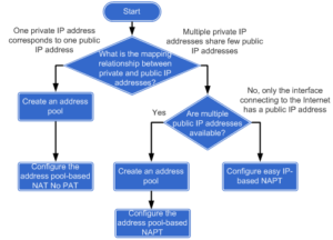
It easily lets us to choose a suitable way of configuring outbound NAT. In this lab I will try to do a review of these methods.
Let’s look at the topology:
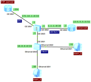
Just forget about FTP server and focus on the bottom of the topology. We will use the FTP server in one of the next articles.
The main requirement in this lab is to configure the firewall, to provide access to the Internet for intranet users, on network segment 10.0.0.0/24.
The configuration of NAT for all above methods is the same. The difference lies in the configuration of NAT address group.
Let’s start!
Set IP addresses of interfaces and add the interfaces to proper security zones:
[SRG]display current-configuration interface GigabitEthernet
#
interface GigabitEthernet0/0/2
 ip address 1.1.1.1 255.255.255.0
#
interface GigabitEthernet0/0/3
#
interface GigabitEthernet0/0/3.100
 vlan-type dot1q 100
 alias GigabitEthernet0/0/3.100
 ip address 10.0.0.1 255.255.255.0
#
[SRG]display current-configuration | begin firewall zone
#
firewall zone trust
 set priority 85
 add interface GigabitEthernet0/0/3.100
#
firewall zone untrust
 set priority 5
 add interface GigabitEthernet0/0/2
Configure L2 communication on the LAN switch:
#
vlan batch 100
#
interface Ethernet0/0/2
 port link-type access
 port default vlan 100
#
interface Ethernet0/0/3
 port link-type access
 port default vlan 100
#
interface GigabitEthernet0/0/1
 port link-type trunk
 port trunk allow-pass vlan 100
Ensure that the users on network segment 10.0.0.0/24 can access the Untrust zone:
[SRG]policy interzone trust untrust outbound
[SRG-policy-interzone-trust-untrust-outbound]policy 1
[SRG-policy-interzone-trust-untrust-outbound-1]policy source 10.0.0.0 mask 24
[SRG-policy-interzone-trust-untrust-outbound-1]action permit
And now the promised configuration of NAT. In this case one private IP address will correspond to one public IP address. To achive it, I will create NAT address group with No-PAT option. NAT No-PAT is also called one-to-one address translation. During the translation, the source IP address of a packet is translated from a private IP address into a public IP address, while the port number is not translated. It means that, when a private network host adopts one public IP address, this address cannot be used by another host because all the ports of public IP address are occupied.
Create NAT address group:
[SRG]nat address-group 1 1.1.1.20 1.1.1.25
Configure NAT policy for the TRUST-UNTRUST interzone, define the range of source IP addresses for NAT and bind the NAT policy to the previousely created NAT address pool:
[SRG]nat-policy interzone trust untrust outbound
[SRG-nat-policy-interzone-trust-untrust-outbound]policy 1
[SRG-nat-policy-interzone-trust-untrust-outbound-1]action source-nat
[SRG-nat-policy-interzone-trust-untrust-outbound-1]policy source 10.0.0.0 mask 24
[SRG-nat-policy-interzone-trust-untrust-outbound-1]address-group 1 no-pat
Let’s verify if it is working correctly. Just try to ping interface loopback of Internet router (5.5.5.5/32) from the both hosts:
User_1>ping 5.5.5.5

Ping 5.5.5.5: 32 data bytes, Press Ctrl_C to break
From 5.5.5.5: bytes=32 seq=1 ttl=254 time=47 ms
From 5.5.5.5: bytes=32 seq=2 ttl=254 time=46 ms
From 5.5.5.5: bytes=32 seq=3 ttl=254 time=63 ms
From 5.5.5.5: bytes=32 seq=4 ttl=254 time=63 ms
From 5.5.5.5: bytes=32 seq=5 ttl=254 time=47 ms

--- 5.5.5.5 ping statistics ---
  5 packet(s) transmitted
  5 packet(s) received
  0.00% packet loss
  round-trip min/avg/max = 46/53/63 ms

User_2>ping 5.5.5.5

Ping 5.5.5.5: 32 data bytes, Press Ctrl_C to break
From 5.5.5.5: bytes=32 seq=1 ttl=254 time=47 ms
From 5.5.5.5: bytes=32 seq=2 ttl=254 time=46 ms
From 5.5.5.5: bytes=32 seq=3 ttl=254 time=62 ms
From 5.5.5.5: bytes=32 seq=4 ttl=254 time=46 ms
From 5.5.5.5: bytes=32 seq=5 ttl=254 time=47 ms

--- 5.5.5.5 ping statistics ---
  5 packet(s) transmitted
  5 packet(s) received
  0.00% packet loss
  round-trip min/avg/max = 46/49/62 ms
Check if the session entry of firewall has been created succesfully:
[SRG]display firewall session table

 Current Total Sessions : 15
  icmp  VPN:public --> public 10.0.0.11:41543[1.1.1.21:41543]-->5.5.5.5:2048
  icmp  VPN:public --> public 10.0.0.10:41031[1.1.1.20:41031]-->5.5.5.5:2048

[SRG]display firewall session table verbose

 Current Total Sessions : 50
  icmp  VPN:public --> public
  Zone: trust--> untrust  TTL: 00:00:20  Left: 00:00:00
  Interface: GigabitEthernet0/0/2  NextHop: 1.1.1.2  MAC: 54-89-98-5c-36-fb
  <--packets:1 bytes:60   -->packets:1 bytes:60
  10.0.0.10:50247[1.1.1.20:50247]-->5.5.5.5:2048

  icmp  VPN:public --> public
  Zone: trust--> untrust  TTL: 00:00:20  Left: 00:00:00
  Interface: GigabitEthernet0/0/2  NextHop: 1.1.1.2  MAC: 54-89-98-5c-36-fb
  <--packets:1 bytes:60   -->packets:1 bytes:60
  10.0.0.11:50247[1.1.1.21:50247]-->5.5.5.5:2048
Check whether the server-map entry is successfully created:
<SRG>display firewall server-map

 server-map item(s)
 ------------------------------------------------------------------------------

 No-Pat, 10.0.0.10[1.1.1.20] -> any, Zone: ---
   Protocol: any(Appro: ---), Left-Time: 00:11:59, Addr-Pool: 1
   VPN: public -> public

 No-Pat Reverse, any -> 1.1.1.20[10.0.0.10], Zone: untrust
   Protocol: any(Appro: ---), Left-Time: --:--:--, Addr-Pool: ---
   VPN: public -> public

 No-Pat, 10.0.0.11[1.1.1.21] -> any, Zone: ---
   Protocol: any(Appro: ---), Left-Time: 00:11:59, Addr-Pool: 1
   VPN: public -> public

 No-Pat Reverse, any -> 1.1.1.21[10.0.0.11], Zone: untrust
   Protocol: any(Appro: ---), Left-Time: --:--:--, Addr-Pool: ---
   VPN: public -> public
Now we can create another NAT address group with only one address available to check NAPT:
#
 nat address-group 2 1.1.1.30 1.1.1.30
#
nat-policy interzone trust untrust outbound
 policy 1
  action source-nat
  policy source 10.0.0.0 mask 24
  address-group 2

[SRG]display firewall session table
 Current Total Sessions : 53
  icmp  VPN:public --> public 10.0.0.10:54605[1.1.1.30:2067]-->5.5.5.5:2048
  icmp  VPN:public --> public 10.0.0.11:55117[1.1.1.30:2070]-->5.5.5.5:2048
And finally NAT easy IP:
#
nat-policy interzone trust untrust outbound
 policy 1
  action source-nat
  policy source 10.0.0.0 mask 24
  easy-ip GigabitEthernet0/0/2
#
[SRG]display firewall session table

 Current Total Sessions : 50
  icmp  VPN:public --> public 10.0.0.10:34127[1.1.1.1:17133]-->5.5.5.5:2048
  icmp  VPN:public --> public 10.0.0.11:34383[1.1.1.1:17134]-->5.5.5.5:2048
If the interface IP address is adopted as the public IP address directly, no NAT address pool is required.

 Huawei AR routers have easy and effective memory usage monitoring tool. When memory usage exceeds configured threshold, the system logs the event and generates an alarm. When memory usage falls within the alarm threshold, the system generates a clear alarm.