Friday , October 18 2024

a few words about BFD

BFD (Bidirectional Forwarding Detection)

What to do to quickly establish an alternative path in case of communication failure between adjacent systems?

There are two detection mechanisms:

  • Hardware detection, for example alarms in SDH used to detect link faults
  • Hello mechanism used by routing protocols.

The main disadvantage of hardware detection is that not all media support it. For example Ethernet does not provide this kind of signalling.

When there is no hardware signalling we can use Hello in routing protocols but this mechanism is relatively slow. Sensitive services, for example voice, cannot work with more than one second delay.

The best solution is to use BFD (Bidirectional Forwarding Detection). This is simple mechanism that works independently of media, data and routing protocols. The main goal of BFD is to detect failures in the path between adjacent devices in a short time (minimum detection time for NE40E is 30ms). It does not matter if it is physical link, virtual circuit, tunnel, MPLS LSP, multi-hop path or unidirectional link. We can treat BFD as a simple Hello protocol where a pair of devices periodically sends BFD packets between them. If one device does not receive BFD packets within specified period, the system assumes that the bidirectional path to the neighboring system has failed.

BFD operates on top of any data protocols creating, deleting and modifying BFD sessions according to information provided by upper layers, at the same time notifying upper layers applications about the session status.

BFD control packets are encapsulated in UDP packet as payload.

BFD provides the following detection modes:

  • Asynchronous mode where 2 devices periodically send BFD packets to each other
  • Query mode where device does not periodically send BFD packets but using for example Hello mechanism of routing protocols for failures’ detection.

Link types detected by BFD:

  • IP links (both one-hop and multi-hop detection)
  • Eth-Trunk
  • VLANIF
  • MPLS LSP
  • PWs

As you already know there are two BFD session modes:

  1. Static BFD where local and remote discriminator are configured manually
  2. Dynamic BFD where system dynamically allocates a “My Discriminator” and then sends a BFD control packet with remote discriminator equals 0. Remote system controls the BFD packet and learns the value of “My Discriminator” as a remote discriminator.

BFD state machine implements a three-way handshake mechanism to establish BFD session.

There are four BFD session states:

  1. DOWN
  2. INIT
  3. UP
  4. AdminDOWN.

Examples of using BFD:

  1. BFD for unicast static route
  2. BFD for routing protocols (OSPF, ISIS, BGP)
  3. BFD for VRRP (virtual router redundancy protocol)
  4. BFD for PST (port state table)
  5. BFD for TE
  6. BFD for PIM
  7. BFD for PW.

This post was only to mention about such mechanism as BFD. As BFD is often being used in current IP networks, for sure you will know how to configure it reading my next posts. At the first opportunity I will show you examples of BFD configuration.

Read More »

Huawei interface backup configuration

There are two interface backup modes:

  1. Active/standby
  2. Load balancing

In common active/standby mode only one interface transmit services at any time. When active interface works properly, it transmit all the traffic. In case of fault of the primary interface, a backup interface with the highest priority starts transmitting packets. If primary interface recovers, traffic is switched back to active interface.

In load balancing mode, in case traffic volume exceeds an upper threshold set for active interface, a backup interface with the highest priority starts transmitting packets and load balancing is performed.

Which mode we have is determined by upper and lower thresholds. If thresholds are not set, active/standby mode is used. Otherwise, load balancing mode is used.

Let’s assume that we have the following topology:

Normally traffic from CE1 router to CE2 router should go through interface GE0/0/1 of RouterA. What we want to do is to configure backup interfaces to ensure that one of them will hand over this traffic in case the active interface is DOWN.

First configure IP addresses and routing between these four routers (below CE1 and RouterA as an example):

CE1 configuration:
#
interface GigabitEthernet0/0/0
 ip address 172.16.10.2 255.255.255.252
#
ip route-static 0.0.0.0 0.0.0.0 172.16.10.1

RouterA configuration:
#
interface GigabitEthernet0/0/0
 ip address 172.16.10.1 255.255.255.252
#
interface GigabitEthernet0/0/1
 undo shutdown
 ip address 10.0.0.1 255.255.255.252
#
interface GigabitEthernet0/0/2
 ip address 10.0.0.5 255.255.255.252
#
interface GigabitEthernet0/0/3
 ip address 10.0.0.9 255.255.255.252
#
ip route-static 172.16.10.12 255.255.255.252 10.0.0.6
ip route-static 172.16.10.12 255.255.255.252 10.0.0.10
ip route-static 172.16.10.12 255.255.255.252 10.0.0.2

Displaying routing table of RouterA we can see that a network 172.16.10.12 is available through these 3 configured static routes:

[RouterA]display ip routing-table
Route Flags: R - relay, D - download to fib
------------------------------------------------------------------------------
Routing Tables: Public
        Destinations : 11       Routes : 13

Destination/Mask    Proto  Pre  Cost       Flags NextHop         Interface

       10.0.0.0/30  Direct 0    0            D   10.0.0.1        GigabitEthernet0/0/1
       10.0.0.1/32  Direct 0    0            D   127.0.0.1       InLoopBack0
       10.0.0.4/30  Direct 0    0            D   10.0.0.5        GigabitEthernet0/0/2
       10.0.0.5/32  Direct 0    0            D   127.0.0.1       InLoopBack0
       10.0.0.8/30  Direct 0    0            D   10.0.0.9        GigabitEthernet0/0/3
       10.0.0.9/32  Direct 0    0            D   127.0.0.1       InLoopBack0
      127.0.0.0/8   Direct 0    0            D   127.0.0.1       InLoopBack0
      127.0.0.1/32  Direct 0    0            D   127.0.0.1       InLoopBack0
    172.16.10.0/30  Direct 0    0            D   172.16.10.1     GigabitEthernet0/0/0
    172.16.10.1/32  Direct 0    0            D   127.0.0.1       InLoopBack0
   172.16.10.12/30  Static 60   0           RD   10.0.0.6        GigabitEthernet0/0/2
                    Static 60   0           RD   10.0.0.10       GigabitEthernet0/0/3
                    Static 60   0           RD   10.0.0.2        GigabitEthernet0/0/1

Now we can configure backup interface on interface GE0/0/1 of RouterA:

#
interface GigabitEthernet0/0/1
 standby interface GigabitEthernet0/0/2 60
 standby interface GigabitEthernet0/0/3 30
#

Look what we can see now. Backup interfaces are in DOWN state. Only active interface is UP:

[RouterA-GigabitEthernet0/0/1]display ip interface brief
*down: administratively down
!down: FIB overload down
(l): loopback
(s): spoofing
The number of interface that is UP in Physical is 3
The number of interface that is DOWN in Physical is 2
The number of interface that is UP in Protocol is 3
The number of interface that is DOWN in Protocol is 2

Interface                         IP Address/Mask      Physical   Protocol
GigabitEthernet0/0/0              172.16.10.1/30       up         up
GigabitEthernet0/0/1              10.0.0.1/30          up         up
GigabitEthernet0/0/2              10.0.0.5/30          down       down
GigabitEthernet0/0/3              10.0.0.9/30          down       down
NULL0                             unassigned           up         up(s)

In IP routing table we have only one static route:

[RouterA]display ip routing-table
Route Flags: R - relay, D - download to fib
------------------------------------------------------------------------------
Routing Tables: Public
        Destinations : 7        Routes : 7

Destination/Mask    Proto  Pre  Cost       Flags NextHop         Interface

       10.0.0.0/30  Direct 0    0            D   10.0.0.1        GigabitEthernet0/0/1
       10.0.0.1/32  Direct 0    0            D   127.0.0.1       InLoopBack0
      127.0.0.0/8   Direct 0    0            D   127.0.0.1       InLoopBack0
      127.0.0.1/32  Direct 0    0            D   127.0.0.1       InLoopBack0
    172.16.10.0/30  Direct 0    0            D   172.16.10.1     GigabitEthernet0/0/0
    172.16.10.1/32  Direct 0    0            D   127.0.0.1       InLoopBack0
   172.16.10.12/30  Static 60   0           RD   10.0.0.2        GigabitEthernet0/0/1

Trace from CE1 to CE2 shows that traffic is going through active interface of RouterA (GE0/0/1):

<CE1>tracert 172.16.10.14
 traceroute to  172.16.10.14(172.16.10.14), max hops: 30 ,packet length: 40
 1 172.16.10.1 30 ms  50 ms  40 ms
 2 10.0.0.2 80 ms  80 ms  50 ms
 3 172.16.10.14 80 ms  90 ms  90 ms

Now we can shutdown interface GE0/0/1 of RouterA:

[RouterA-GigabitEthernet0/0/1]shutdown

[RouterA-GigabitEthernet0/0/1]display this
interface GigabitEthernet0/0/1
 shutdown
 ip address 10.0.0.1 255.255.255.252
 standby interface GigabitEthernet0/0/2 60
 standby interface GigabitEthernet0/0/3 30

Now traffic from CE1 to CE2 is going through GE0/0/2 of RouterA:

<CE>tracert 172.16.10.14
 traceroute to  172.16.10.14(172.16.10.14), max hops: 30 ,packet length: 40
 1 172.16.10.1 30 ms  30 ms  50 ms
 2 10.0.0.6 80 ms  60 ms  50 ms
 3 172.16.10.14 110 ms  100 ms  100 ms

What we can see on RouterA is:

[RouterA]display ip routing-table
Route Flags: R - relay, D - download to fib
------------------------------------------------------------------------------
Routing Tables: Public
        Destinations : 7        Routes : 7

Destination/Mask    Proto  Pre  Cost       Flags NextHop         Interface

       10.0.0.4/30  Direct 0    0            D   10.0.0.5        GigabitEthernet0/0/2
       10.0.0.5/32  Direct 0    0            D   127.0.0.1       InLoopBack0
      127.0.0.0/8   Direct 0    0            D   127.0.0.1       InLoopBack0
      127.0.0.1/32  Direct 0    0            D   127.0.0.1       InLoopBack0
    172.16.10.0/30  Direct 0    0            D   172.16.10.1     GigabitEthernet0/0/0
    172.16.10.1/32  Direct 0    0            D   127.0.0.1       InLoopBack0
   172.16.10.12/30  Static 60   0           RD   10.0.0.6        GigabitEthernet0/0/2

[RouterA]display standby state
Interface            Interfacestate Backupstate Backupflag Pri Loadstate
GigabitEthernet0/0/1         DOWN    MDOWN      MU
GigabitEthernet0/0/2         UP      UP         BU          60
GigabitEthernet0/0/3         STANDBY STANDBY    BU          30

 Backup-flag meaning:
 M---MAIN  B---BACKUP     V---MOVED    U---USED
 D---LOAD  P---PULLED     G---LOGICCHANNEL

As we can see active interface is now in DOWN state, one of backup interfaces is UP and the second backup interface is in standby state.

To speed up switching between active and backup interfaces, we can associate interface backup with BFD. BFD provides fast fault detection of the primary link and reports faults to the interface backup module. Then traffic is switched to the backup link. We can do this in ARx2 routers. NE routers do not support BFD with backup interface association.

Read More »

how to display electronic labels

display elabel [ backplane | slot-id ]

Using this command lets you to display electronic labels of the boards installed. If you do not specify slot-id you will see information about all the boards. An output of this command includes among others:

  • type of boards and PIC cards
  • bar code
  • English description
  • BOM
  • vendor’s name.

Read More »

Huawei basic user environment

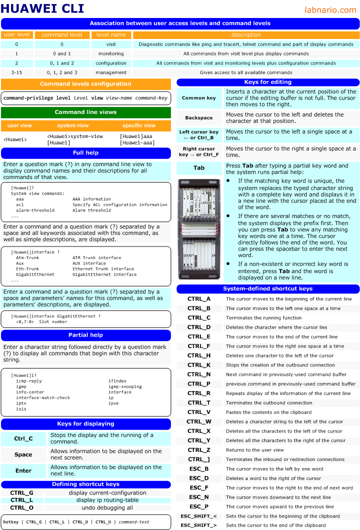
As you already know you can assign a different privilege level for each user, configured on a Huawei device. How to configure local user and how to access Huawei device you can read in one of my previous posts.

user privilege level

Today I want to focus on the privilege level of local user. Each year lots of accidents in IP networks are caused by inexperienced employees. We can decrease the number of such accidents setting privilege level for local users, logging into network devices. Setting a lower privilege level for such employees increases networks’ safety. For more experienced engineers  we can either configure higher privilege level or set a super password, to let them to perform advanced operation.

Let’s assume that we have created a local user with the lowest priority:

#
local-user labnario password cipher &EU15O"Q3/;Q=^Q`MAF4<1!!
 local-user labnario service-type telnet
 local-user labnario level 0
#

After you are logged as user “labnario” and putting a question mark you can see all commands available in level 0:

<CX600>?
User view commands:
  cluster        Run cluster command
  display        Display LPUF-10 work-mode
  hwtacacs-user  HWTACACS user
  language-mode  Specify the language environment
  local-user     Local user
  ping           Ping function
  quit           Exit from current command view
  return         Exit to user view
  save           Save file
  super          Privilege current user a specified priority level
  telnet         Establish a Telnet connection
  trace          Trace route (switch) to host on Data Link Layer
  tracert        Trace route to host

As this is the lowest privilege level we cannot even display current-configuration and interfaces’ statistics:

<CX600>display current-configuration
             ^
Error: Unrecognized command found at '^' position.

<CX600>display interface GigabitEthernet7/0/0
             ^
Error: Unrecognized command found at '^' position.
command privilege level

But we can assign additional commands to this level in advance, as needed:

#
command-privilege level 0 view shell display current-configuration
command-privilege level 0 view system display current-configuration
command-privilege level 0 view shell display interface GigabitEthernet7/0/0
#

Now it is possible to display current-configuration and statistics of GE7/0/0:

<CX600>display ?
  current-configuration     Current configuration
  interface                 Status and configuration information for the
                            interface
super password and switching user levels

Let’s come back to super password. What we want to do is to the set super password, in advance, for privilege level 15:

[CX600]super password level 15 cipher &EU15O"Q3/;Q=^Q`MAF4<1!!

And now if you are logged as level 0 user, you can switch to level 15. If you want to recall about a level’s arrangement on Huawei devices you can read huawei cli introduction.

<CX600>super 15
Password:
Now user privilege is 15 level, and only those commands whose level is equal to or less than this level can be used.
Privilege note: 0-VISIT, 1-MONITOR, 2-SYSTEM, 3-MANAGE

Now you have full rights to configure and manage this device.

locking user terminal

Remember to lock your current user terminal interface if you are away of your desk. It prevents your device against unauthorized users operations on the current terminal interface:

<CX600>lock
Enter Password:
Confirm Password:

Info: The terminal is locked.

Enter Password:
<CX600>

Read More »

from Huawei CLI – header …

header { login | shell }

login – header text is displayed after you are trying to log into a device

shell – header text is displayed after you are successfully logged into a device

Example of configuring header login by using plain text:
[labnario]header login information %
The banner text supports 220 characters max, including the start and
the end character.If you want to enter more than this, use banner file
instead.Input banner text, and quit with the character '%':
welcome to labnario network lab!!!%

Remember that the initial and end characters must be the same. In this case % has been used. The interaction starts after you put % and then enter and automatically closes when you write your header text and put % again.

And now if you want to log into the device by telnet or ssh you will see the following prompt:

welcome to labnario network lab!!!

Login authentication

Username:

You will achieve the same result when you use the following command:

[labnario]header login file header.txt

But the only thing you have to remember about is to create this header.txt file and place it in memory of the device (flash or CFcard). How to upload files by FTP I was describing in the following post.

Read More »