That was to be expected. Poland is out of Euro Cup. The only thing we can do is to come back to the real world :).
Today I will show you how to use ACLs and traffic policies for packets’ lost troubleshooting in a network.
Huawei ACL and traffic policy configuration
Let’s assume that we have such topology:
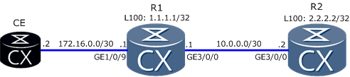
What we have to do is to check end-to-end connectivity between CE and R2 Loopback100 interface, to find where packets are being lost.
- Configure routing protocol to ensure communication between all devices. R1 configuration as an example:
#
interface GigabitEthernet3/0/0
 undo shutdown
 ip address 10.0.0.1 255.255.255.252
#
interface GigabitEthernet1/0/9
 undo shutdown
 ip address 172.16.0.1 255.255.255.252
#
interface LoopBack100
 ip address 1.1.1.1 255.255.255.255
#
ospf 1 router-id 1.1.1.1
 area 0.0.0.0
  network 10.0.0.0 0.0.0.3
  network 1.1.1.1 0.0.0.0
  network 172.16.0.0 0.0.0.3
#
- Configure ACL that permits ICMP traffic from CE to R2 Loopback100 IP address and from R2 to CE (the same ACL for R1 and R2):
#
acl number 3000
 rule 5 permit icmp source 172.16.0.0 0.0.0.3 destination 2.2.2.2 0
 rule 10 permit icmp source 2.2.2.2 0 destination 172.16.0.0 0.0.0.3
#
- Configure traffic policy that permits traffic matched by the ACL (the same for R1 and R2):
#
traffic classifier labnario operator or
 if-match acl 3000
#
traffic behavior labnario
#
traffic policy labnario
 statistics enable
 classifier labnario behavior labnario
#
Notice that default behaviour for the traffic is to permit (default parameters are not displayed in configuration). Remember to use “statistics enable” command to be able to display traffic policy statistics.
- Assign this traffic policy to all interfaces on the path between CE and R2 (for both inbound and outbound direction):
R1:
#
interface GigabitEthernet1/0/9
 undo shutdown
 ip address 172.16.0.1 255.255.255.252
 traffic-policy labnario inbound
 traffic-policy labnario outbound
#
interface GigabitEthernet3/0/0
 undo shutdown
 ip address 10.0.0.1 255.255.255.252
 traffic-policy labnario inbound
 traffic-policy labnario outbound
R2:
#
interface GigabitEthernet3/0/0
 undo shutdown
 ip address 10.0.0.2 255.255.255.252
 traffic-policy labnario inbound
 traffic-policy labnario outbound
- Ping from CE to R2 Loopback100 IP address:
<CE>ping -c 100 -t 100 2.2.2.2
  PING 2.2.2.2: 56  data bytes, press CTRL_C to break
    Reply from 2.2.2.2: bytes=56 Sequence=1 ttl=254 time=15 ms
    Reply from 2.2.2.2: bytes=56 Sequence=2 ttl=254 time=10 ms
    Reply from 2.2.2.2: bytes=56 Sequence=3 ttl=254 time=10 ms
    .
    .
    .
    Reply from 2.2.2.2: bytes=56 Sequence=100 ttl=254 time=21 ms

  --- 2.2.2.2 ping statistics ---
    100 packet(s) transmitted
    100 packet(s) received
    0.00% packet loss
    round-trip min/avg/max = 9/12/52 ms
- Display traffic policy statistics for all interfaces on the path between CE and R2 (for inbound and outbound):
R1:
<R1>display traffic policy statistics interface GigabitEthernet 1/0/9 inbound verbose rule-based
Info: The statistics is shared because the policy is shared.
Interface: GigabitEthernet1/0/9
Traffic policy inbound: labnario
Traffic policy applied at 2012-06-20 10:31:42
Statistics enabled at 2012-06-20 10:31:42
Statistics last cleared: 2012-06-20 11:42:42
Rule number: 5 IPv4, 0 IPv6
Current status: OK!

Classifier: labnario operator or
 if-match ACL 3000
  rule 5 permit icmp source 172.16.0.0 0.0.0.3 destination 2.2.2.2 0
    10,200 bytes, 100 packets
    Last 30 seconds rate 0 pps, 0 bps
  rule 10 permit icmp source 2.2.2.2 0 destination 172.16.0.0 0.0.0.3
    0 bytes, 0 packets
    Last 30 seconds rate 0 pps, 0 bps

<R1>display traffic policy statistics interface GigabitEthernet 1/0/9 outbound verbose rule-based
Info: The statistics is shared because the policy is shared.
Interface: GigabitEthernet1/0/9
Traffic policy outbound: labnario
Traffic policy applied at 2012-06-20 10:31:45
Statistics enabled at 2012-06-20 10:31:45
Statistics last cleared: 2012-06-20 11:42:45
Rule number: 5 IPv4, 0 IPv6
Current status: OK!

Classifier: labnario operator or
 if-match ACL 3000
  rule 5 permit icmp source 172.16.0.0 0.0.0.3 destination 2.2.2.2 0
    0 bytes, 0 packets
    Last 30 seconds rate 0 pps, 0 bps
  rule 10 permit icmp source 2.2.2.2 0 destination 172.16.0.0 0.0.0.3
    10,200 bytes, 100 packets
    Last 30 seconds rate 0 pps, 0 bps

<R1>display traffic policy statistics interface GigabitEthernet 3/0/0 inbound verbose rule-based
Info: The statistics is shared because the policy is shared.
Interface: GigabitEthernet3/0/0
Traffic policy inbound: labnario
Traffic policy applied at 2012-06-19 14:02:40
Statistics enabled at 2012-06-19 14:02:40
Statistics last cleared: 2012-06-20 11:43:40
Rule number: 5 IPv4, 0 IPv6
Current status: OK!

Classifier: labnario operator or
 if-match ACL 3000
  rule 5 permit icmp source 172.16.0.0 0.0.0.3 destination 2.2.2.2 0
    0 bytes, 0 packets
    Last 30 seconds rate 0 pps, 0 bps
  rule 10 permit icmp source 2.2.2.2 0 destination 172.16.0.0 0.0.0.3
    10,200 bytes, 100 packets
    Last 30 seconds rate 0 pps, 0 bps

<R1>display traffic policy statistics interface GigabitEthernet 3/0/0 outbound verbose rule-based
Info: The statistics is shared because the policy is shared.
Interface: GigabitEthernet3/0/0
Traffic policy outbound: labnario
Traffic policy applied at 2012-06-19 14:02:43
Statistics enabled at 2012-06-19 14:02:43
Statistics last cleared: 2012-06-20 11:43:36
Rule number: 5 IPv4, 0 IPv6
Current status: OK!

Classifier: labnario operator or
 if-match ACL 3000
  rule 5 permit icmp source 172.16.0.0 0.0.0.3 destination 2.2.2.2 0
    10,200 bytes, 100 packets
    Last 30 seconds rate 0 pps, 0 bps
  rule 10 permit icmp source 2.2.2.2 0 destination 172.16.0.0 0.0.0.3
    0 bytes, 0 packets
    Last 30 seconds rate 0 pps, 0 bps
R2:
<R2>display traffic policy statistics interface GigabitEthernet 3/0/0 inbound verbose rule-based
Info: The statistics is shared because the policy is shared.
Interface: GigabitEthernet3/0/0
Traffic policy inbound: labnario
Traffic policy applied at 2000-01-01 00:32:07
Statistics enabled at 2000-01-01 00:49:04
Statistics last cleared: 2000-01-01 23:20:42
Rule number: 5 IPv4, 0 IPv6
Current status: OK!

Classifier: labnario operator or
 if-match ACL 3000
  rule 5 permit icmp source 172.16.0.0 0.0.0.3 destination 2.2.2.2 0
    10,200 bytes, 100 packets
    Last 30 seconds rate 0 pps, 0 bps
  rule 10 permit icmp source 2.2.2.2 0 destination 172.16.0.0 0.0.0.3
    0 bytes, 0 packets
    Last 30 seconds rate 0 pps, 0 bps

<R2>display traffic policy statistics interface GigabitEthernet 3/0/0 outbound verbose rule-based
Info: The statistics is shared because the policy is shared.
Interface: GigabitEthernet3/0/0
Traffic policy outbound: labnario
Traffic policy applied at 2000-01-01 01:41:43
Statistics enabled at 2000-01-01 01:41:43
Statistics last cleared: 2000-01-01 23:20:39
Rule number: 5 IPv4, 0 IPv6
Current status: OK!

Classifier: labnario operator or
 if-match ACL 3000
  rule 5 permit icmp source 172.16.0.0 0.0.0.3 destination 2.2.2.2 0
    0 bytes, 0 packets
    Last 30 seconds rate 0 pps, 0 bps
  rule 10 permit icmp source 2.2.2.2 0 destination 172.16.0.0 0.0.0.3
    10,200 bytes, 100 packets
    Last 30 seconds rate 0 pps, 0 bps
As you can see from these outputs, packets are not being lost in the network. In case of any network problem you can use a similar traffic policy to find where packets are being lost. Of course this is one of the examples of using traffic policy. You can, for instance, use it to catch packets classified based on DSCP, 802.1p etc. I can say I use it very often in a routine work, not only for troubleshooting but also in another applications.
This example was done based on NE40E V600R001SPC800 software. Traffic policy configuration can vary depending on the devices and software you use.
Read More »