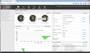
A new box for fun 🙂
Thanks to my colleagues I have opportunity to test Huawei Secospace USG6300.
A rental period is not long, so let’s start from the beginning.
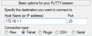
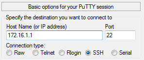
Telnet and SSH

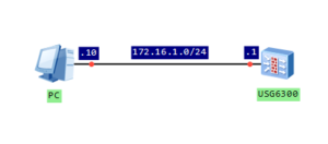
Configure IP address of firewall’s interface and assign it to trust zone:
[USG6300]interface GigabitEthernet 0/0/7
[USG6300-GigabitEthernet0/0/7]ip address 172.16.1.1 24

[USG6300]firewall zone trust
[USG6300-zone-trust]add interface GigabitEthernet 0/0/7
Enable telnet and SSH services on that interface:
[USG6300]interface GigabitEthernet 0/0/7
[USG6300-GigabitEthernet0/0/7]service-manage telnet permit
[USG6300-GigabitEthernet0/0/7]service-manage ssh permit
Create local users for telnet and SSH access:
[USG6300]aaa
[USG6300-aaa]manager-user vty_labnario
[USG6300-aaa-manager-user-vty_labnario]password cipher Labnario123
[USG6300-aaa-manager-user-vty_labnario]service-type telnet
[USG6300-aaa-manager-user-vty_labnario]level 15

#
 manager-user ssh_labnario
  password cipher %@%@*;-$=&1LSK4n^9Tn)Ny!H,#w3&0~LrT%*W@gFyXV4LT,"2)$%@%@
  service-type ssh
  level 15
  ftp-directory hda1:
  ssh authentication-type password
  ssh service-type stelnet
 #
Set authentication method for VTY interfaces:
[USG6300]user-interface vty 0 4
[USG6300-ui-vty0-4]authentication-mode aaa
Enable servers for configured services:
[USG6300]telnet server enable
[USG6300]stelnet server enable
To complete SSH configuration, create RSA key:
[USG6300]rsa local-key-pair create
12:06:32  2015/03/31
The key name will be: USG6300_Host
The range of public key size is (512 ~ 2048).
NOTES: A key shorter than 2048 bits may cause security risks.
       The generation of a key longer than 512 bits may take several minutes.
Input the bits in the modulus[default = 2048]:
Generating keys...
.+++
.............+++
.............++++++++
.............++++++++

[USG6300]
Let’s verify access to the device:
***********************************************************
*           All rights reserved 2014                      *
*       Without the owner's prior written consent,        *
* no decompiling or reverse-engineering shall be allowed. *
* Notice:                                                 *
*      This is a private communication system.            *
*   Unauthorized access or use may lead to prosecution.   *
***********************************************************

Warning: Telnet is not a secure protocol, and it is recommended to use Stelnet.

Login authentication


Username:vty_labnario
Password:
Note: The max number of VTY users is 5, and the current number
      of VTY users on line is 1.
NOTICE:This is a private communication system.
       Unauthorized access or use may lead to prosecution.
<USG6300>
First time login or password is overtime, Please change your password.
Please input new password:**********
Please confirm new password:**********
Note: The max number of VTY users is 5, and the current number
      of VTY users on line is 1.
NOTICE:This is a private communication system.
       Unauthorized access or use may lead to prosecution.
<USG6300>
login as: ssh_labnario
ssh_labnario@172.16.1.1's password:

***********************************************************
*           All rights reserved 2014                      *
*       Without the owner's prior written consent,        *
* no decompiling or reverse-engineering shall be allowed. *
* Notice:                                                 *
*      This is a private communication system.            *
*   Unauthorized access or use may lead to prosecution.   *
***********************************************************

Note: The max number of VTY users is 5, and the current number
      of VTY users on line is 1.
  ----------------------------------------------------------------------------
  User last login information:
  ----------------------------------------------------------------------------
  Access Type: SSH
  IP-Address : 172.16.1.10
  Time       : 2015-03-31 12:08:16 +01:00
  State      : Login Succeeded
  ----------------------------------------------------------------------------
<USG6300>
Note: The max number of VTY users is 5, and the current number
      of VTY users on line is 1.
NOTICE:This is a private communication system.
       Unauthorized access or use may lead to prosecution.
<USG6300>
As you could see, password must be changed after the first login. You can disable modifying the password by the command:
[USG6300-aaa]undo manager-user password-modify enable
SFTP
As secure FTP is related to SSH, let’s try to finish this article with SFTP configuration:
#
 manager-user sftp_lab
  password cipher %@%@!siuS<f},>]>IM,2!|,#K!ul&;<u1g4:%'e8[NIfPZF@*'{v%@%@
  service-type ssh
  level 15
  ftp-directory hda1:
  ssh authentication-type password
  ssh service-type sftp
#
[USG6300]sftp server enable
Info: Succeeded in starting the SFTP server.
To verify, we can use PSFTP software:
psftp> open 172.16.1.1
login as: sftp_lab
Using username "sftp_lab".
sftp_lab/172.16.1.1's password:
Remote working directory is /
psftp>
Read More »
 Huawei AR routers have easy and effective CPU usage monitoring tool. They generate alarm, when CPU usage reaches 80%. When CPU usage falls to 75%, recovery usage alarm is generated again (clear alarm). This is a default behaviour, but these values can be easily changed in order to help optimize system performance and ensure system stability.