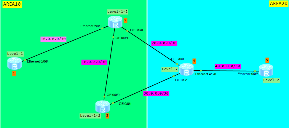
Friday , September 20 2024

local attack defense on Huawei AR routers

Let’s assume that a large number of packets are sent to CPU of a device. What will happen if most of these packets are malicious attack packets? CPU usage will become high, what can bring to services’ deterioration. In extreme cases it can lead the device to reboot. We can minimize an impact of the attack on network services, providing the local attack defense function. When such attack occurs, this function ensures non-stop service transmission.

Attack Defense Policy Supported by AR routers:

CPU attack defense:
  • The device uses blacklists to filters invalid packets sent to the CPU
  • The device limits the rate of packets sent to the CPU based on the protocol type
  • The device schedules packets sent to the CPU based on priorities of protocol packets
  • The device uniformly limits the rate of packets with the same priority sent to the CPU and randomly discards the excess packets to protect the CPU
  • ALP is enabled to protect HTTP, FTP and BGP sessions. Packets matching characteristics of the sessions are sent at a high rate, that’s why session-related services are ensured.

Attack source tracing:
  • Attack source tracing checks attack packets sent to the CPU and notifies the administrator by sending logs or alarms so that the administrator can take measures to defend against attacks.

Although each device has the defult configuration of local attack defense policy, you can change it every time you need.

Based on AR documentation:

Default configuration of attack source tracing:

Default configuration of CPU attack defense:

Configuring attack source tracing:

Creating an attack defense policy:

cpu-defend policy policy-name (max 19 attack defense policies including the defualt)

Configuring the threshold for attack source tracing:

auto-defend enable
auto-defend threshold threshold-value

Configuring the alarm function for attack source tracing:

auto-defend alarm enable
auto-defend alarm threshold threshold-value
Configuring CPU Attack Defense:

Configuring a blacklist:

blacklist blacklist-id acl acl-number (how to configure ACL)

Configuring the rate limit for packets sent to the CPU:

packet-type packet-type rate-limit rate-value (excess packets are discarded)

deny packet-type packet-type (discards all packets)

Setting the priority for packets of a specified protocol:

packet-type packet-type priority priority-level

Configuring ALP:

application-apperceive packet-type { bgp | ftp | http } rate-limit rate-value

Configuring the rate limit for all packets sent to the CPU:

rate-limit all-packets pps pps-value

Applying the attack defense policy:

cpu-defend-policy policy-name [ global | slot slot-id ]

[AR3200]cpu-defend-policy labnario (apply the CPU attack defense policy to the SRU)

[AR3200]cpu-defend-policy labnario global (apply the CPU attack defense policy to the LPU)

[AR3200]cpu-defend-policy labnario slot  2 (apply the CPU attack defense policy to slot 2)

Useful maintenace commands:

  • display auto-defend attack-source
  • display auto-defend configuration
  • display cpu-defend policy
  • display cpu-defend policy
  • display cpu-defend statistics
  • display cpu-defend configuration.

Read More »

equivalent of Cisco Private Vlan —> Huawei MUX Vlan

Do you know the Private VLAN feature from Cisco switches? The same feature exists on Huawei switches and is called the MUX VLAN.

How does this feature work?

MUX VLAN allows isolating Layer2 traffic of different interfaces in the same VLAN, and still allowing access to common resources.

Look at the topology below. Let’s assume that we want to configure our labnariosw switch, so that:

  • hosts in VLAN10 should be able to ping each other and ping server in VLAN30
  • hosts in VLAN20 should be able to ping server in VLAN30 but not each other
  • hosts in VLAN10 should not be able to ping hosts in VLAN20.

To do so, we need to define:

  • VLAN30 as a “principal VLAN” and add interface connecting server to this VLAN
  • VLAN10 as a “seprate VLAN” and add user interfaces to it
  • VLAN20 as a “group VLAN” and add user interfaces to this VLAN.

Let’s start configuring our topology. As the first step VLANs 10, 20 and 30 should be configured:

<labnariosw>sys
Enter system view, return user view with Ctrl+Z.
[labnariosw]vlan batch 10 20 30
Info: This operation may take a few seconds. Please wait for a moment...done.

VLAN30 should be defined as a principal, VLAN 10 as a group VLAN, and 20 as a separate VLAN:

[labnariosw]vlan 30
[labnariosw-vlan30]mux-vlan
[labnariosw-vlan30]subordinate group 10
[labnariosw-vlan30]subordinate separate 20

As the last step, switch ports have to be added to the appropriate VLAN and MUX VLAN feature have to be enabled as follows:

[labnariosw]interface Ethernet0/0/1	
[labnariosw-Ethernet0/0/1]port link-type access
[labnariosw-Ethernet0/0/1]port default vlan 10
[labnariosw-Ethernet0/0/1]port mux-vlan enable
[labnariosw]interface Ethernet0/0/2
[labnariosw-Ethernet0/0/1]port link-type access
[labnariosw-Ethernet0/0/1]port default vlan 10
[labnariosw-Ethernet0/0/1]port mux-vlan enable
[labnariosw]interface Ethernet0/0/3
[labnariosw-Ethernet0/0/1]port link-type access
[labnariosw-Ethernet0/0/1]port default vlan 20
[labnariosw-Ethernet0/0/1]port mux-vlan enable
[labnariosw]interface Ethernet0/0/4
[labnariosw-Ethernet0/0/1]port link-type access
[labnariosw-Ethernet0/0/1]port default vlan 20
[labnariosw-Ethernet0/0/1]port mux-vlan enable
[labnariosw]interface Ethernet0/0/5	
[labnariosw-Ethernet0/0/1]port link-type access
[labnariosw-Ethernet0/0/1]port default vlan 30
[labnariosw-Ethernet0/0/1]port mux-vlan enable

That’s all. Some verification commands:

[labnariosw]display vlan 
The total number of vlans is : 4
--------------------------------------------------------------------------------

U: Up;         D: Down;         TG: Tagged;         UT: Untagged;
MP: Vlan-mapping;               ST: Vlan-stacking;
#: ProtocolTransparent-vlan;    *: Management-vlan;
--------------------------------------------------------------------------------

VID  Type    Ports                
--------------------------------------------------------------------------------
1    common  UT:Eth0/0/6(D)     Eth0/0/7(D)     Eth0/0/8(D)     Eth0/0/9(D)     
                Eth0/0/10(D)    Eth0/0/11(D)    Eth0/0/12(D)    Eth0/0/13(D)    
                Eth0/0/14(D)    Eth0/0/15(D)    Eth0/0/16(D)    Eth0/0/17(D)    
                Eth0/0/18(D)    Eth0/0/19(D)    Eth0/0/20(D)    Eth0/0/21(D)    
                Eth0/0/22(D)    GE0/0/1(D)      GE0/0/2(D)                      
10   mux-sub UT:Eth0/0/1(U)     Eth0/0/2(U)                                   
20   mux-sub UT:Eth0/0/3(U)     Eth0/0/4(U)                                     
30   mux     UT:Eth0/0/5(U)           

VID  Status  Property      MAC-LRN Statistics Description      
--------------------------------------------------------------------------------
1    enable  default       enable  disable    VLAN 0001                         
10   enable  default       enable  disable    VLAN 0010                         
20   enable  default       enable  disable    VLAN 0020                         
30   enable  default       enable  disable    VLAN 0030

[labnariosw]display mux-vlan 
Principal Subordinate Type         Interface  
-----------------------------------------------------------------------------
30        -           principal    Ethernet0/0/5
30        20          separate     Ethernet0/0/3 Ethernet0/0/4
30        10          group        Ethernet0/0/1 Ethernet0/0/2
-----------------------------------------------------------------------------

Now the ping test can be done to verify if our MUX VLAN configuration is working (do not forget to address your PCs).

Hosts in VLAN10 should be able to ping each other and ping server in VLAN30:

PC1>ping 192.168.100.2

Ping 192.168.100.2: 32 data bytes, Press Ctrl_C to break
From 192.168.100.2: bytes=32 seq=1 ttl=128 time=15 ms
From 192.168.100.2: bytes=32 seq=2 ttl=128 time=32 ms
From 192.168.100.2: bytes=32 seq=3 ttl=128 time=47 ms
…

PC1>ping 192.168.100.100

Ping 192.168.100.100: 32 data bytes, Press Ctrl_C to break
From 192.168.100.100: bytes=32 seq=1 ttl=128 time=15 ms
From 192.168.100.100: bytes=32 seq=2 ttl=128 time=30 ms
From 192.168.100.100: bytes=32 seq=3 ttl=128 time=16 ms
…

Hosts in VLAN20 should be able to ping server in VLAN30 but not be able to ping each other.

PC3>ping 192.168.100.100

Ping 192.168.100.100: 32 data bytes, Press Ctrl_C to break
From 192.168.100.100: bytes=32 seq=1 ttl=128 time=43 ms
From 192.168.100.100: bytes=32 seq=2 ttl=128 time=46 ms
From 192.168.100.100: bytes=32 seq=3 ttl=128 time=15 ms
…

PC4>ping 192.168.100.100

Ping 192.168.100.100: 32 data bytes, Press Ctrl_C to break
From 192.168.100.100: bytes=32 seq=1 ttl=128 time=43 ms
From 192.168.100.100: bytes=32 seq=2 ttl=128 time=46 ms
From 192.168.100.100: bytes=32 seq=3 ttl=128 time=15 ms
…

PC3>ping 192.168.100.4
Ping 192.168.100.4: 32 data bytes, Press Ctrl_C to break
    Request time out
    Request time out
    Request time out
…

Hosts in VLAN10 should not be able to ping hosts in VLAN20.

PC1>ping 192.168.100.3
Ping 192.168.100.3: 32 data bytes, Press Ctrl_C to break
    Request time out
    Request time out
    Request time out
…

PC1>ping 192.168.100.4
Ping 192.168.100.4: 32 data bytes, Press Ctrl_C to break
    Request time out
    Request time out
    Request time out
…

PC2>ping 192.168.100.3
Ping 192.168.100.3: 32 data bytes, Press Ctrl_C to break
    Request time out
    Request time out
    Request time out
…

PC2>ping 192.168.100.4
Ping 192.168.100.4: 32 data bytes, Press Ctrl_C to break
    Request time out
    Request time out
    Request time out
…

Read More »

how to find TC packets source on Huawei switch

Topology Change (TC) packets are sent when MSTP-enabled interface in a network flaps. If a physical interface frequently alternates between Up and Down, the MSTP status of the device in the network becomes unsteady. As a result, a large number of TC messages are generated, ARP entries are frequently deleted and services are interrupted.

How to find the source of TC packets?

Let’s look at the log, generated on one of the switches in a network. Let’s take Huawei S9300 switch as an example:

Dec 19 2012 11:32:56+10:00 S9300 %%01MSTP/6/RECEIVE_MSTITC(l)[40922]:MSTP received BPDU with TC, MSTP process 0 instance 0, port name is GigabitEthernet6/0/0.

What can we find in this log?

The most important for us is the port number on which the switch received TC packet, in this case interface GE6/0/0. To troubleshoot this problem we have to go to the next switch, connected to interface GE6/0/0 and check logs of that switch. If the neighbouring switch receives TC packets as well, we have to do further troubleshooting. If we find in the logs that MSTP-enabled interface is flapping, we can consider that this interface is the source of the TC packet. If this interface is still flapping, just make it down, to avoid unsteady behaviour.

To check whether the device has received TC messages:

[S9300] display stp 
-------[CIST Global Info][Mode MSTP]-------
CIST Bridge         :57344.00e0-fc00-1597
Bridge Times        :Hello 2s MaxAge 20s FwDly 15s MaxHop 20
CIST Root/ERPC      :0    .0018-826f-fc7a / 20000
CIST RegRoot/IRPC   :57344.00e0-fc00-1597 / 0
CIST RootPortId     :128.2
BPDU-Protection     :disabled
TC or TCN received  :0
TC count per hello  :0
STP Converge Mode   :Nomal
Time since last TC :2 days 14h:16m:15s    

-------[MSTI 1 Global Info]-------
MSTI Bridge ID      :4096.00e0-fc00-1597
MSTI RegRoot/IRPC   :4096.00e0-fc00-1597 / 0
MSTI RootPortId     :0.0
Master Bridge       :57344.00e0-fc00-1597
Cost to Master      :0
TC received         :0
TC count per hello  :2

If a switch receives lots of TC packets, please run the following hidden command several times to check and compare which ports receive a large number of TC packets:

[S9300]_h (enter into hidden mode)
[S9300-hidecmd]display stp tc (in V1R3 software version)
 ---------- Stp Instance 0 tc or tcn count ----------
 Port GigabitEthernet3/0/0    0
 Port GigabitEthernet3/0/1    4
 Port GigabitEthernet4/0/2    2
 Port GigabitEthernet4/0/3    0
 Port GigabitEthernet6/0/0    8
 Port GigabitEthernet6/0/1    0

[S9300-hidecmd]display stp tc-bpdu statistics (in V1R6 software version)
 -------------------------- STP TC/TCN information --------------------------
 MSTID Port                        TC(Send/Receive)      TCN(Send/Receive)
 0     GigabitEthernet3/0/0        12/1                  0/0
 0     GigabitEthernet3/0/1        1/0                   0/0
 0     GigabitEthernet4/0/2        4/7                   0/0
 0     GigabitEthernet4/0/3        2/0                   0/0
 0     GigabitEthernet6/0/0        0/10                  0/0
 0     GigabitEthernet6/0/1        0/6                   0/0

We can reset these statistics using the following command:

<S9303>reset stp statistics

Read More »

basic BGP in Huawei CLI – part 2

This article is a continuation of the basic BGP with Huawei CLI.

Today I want to explain you, why labnarioR5 router cannot ping BGP prefixes advertised by BGP AS50. Do you remember our BGP topology? I have configured BGP protocol as in the picture below:


There are three BGP Autonomous Systems: AS50, AS100 and AS55. All are connected via EBGP peering sessions. AS100 has three routers forming IBGP full mesh. LabnarioR1 router in AS50 advertises three prefixes:

  • 11.10.10.0/24
  • 12.10.10.0/24
  • 13.10.10.0/24

All these prefixes are advertised by the routers in AS100 and pass to AS55. LabnarioR5 router has these prefixes in its BGP and routing tables, but cannot ping them. Why is it like that?

As the first step I want to check labnarioR5 router’s routing and BGP tables:

<labnarioR5>dis ip routing-table
Route Flags: R - relay, D - download to fib
------------------------------------------------------------------------------
Routing Tables: Public
         Destinations : 10       Routes : 10       

Destination/Mask    Proto   Pre  Cost      Flags NextHop         Interface

     11.10.10.0/24  EBGP    255  0           D   155.100.35.3    Serial0/0/0  
     12.10.10.0/24  EBGP    255  0           D   155.100.35.3    Serial0/0/0 
     13.10.10.0/24  EBGP    255  0           D   155.100.35.3    Serial0/0/0 
      127.0.0.0/8   Direct  0    0           D   127.0.0.1       InLoopBack0
      127.0.0.1/32  Direct  0    0           D   127.0.0.1       InLoopBack0
   155.100.35.0/24  Direct  0    0           D   155.100.35.5    Serial0/0/0
   155.100.35.3/32  Direct  0    0           D   155.100.35.3    Serial0/0/0
   155.100.35.5/32  Direct  0    0           D   127.0.0.1       Serial0/0/0
   155.100.45.0/24  Direct  0    0           D   155.100.45.5    Ethernet0/0/0
   155.100.45.5/32  Direct  0    0           D   127.0.0.1       Ethernet0/0/0

It looks like labnarioR5 has all three prefixes installed in its routing table. Let’s see BGP table:

<labnarioR5>dis bgp routing-table 

 BGP Local router ID is 155.100.45.5 
 Status codes: * - valid, > - best, d - damped,
               h - history,  i - internal, s - suppressed, S - Stale
               Origin : i - IGP, e - EGP, ? - incomplete

 Total Number of Routes: 6
      Network            NextHop        MED        LocPrf    PrefVal Path/Ogn

 *>   11.10.10.0/24     155.100.35.3                          0      100 50i
 *                      155.100.45.4                          0      100 50i
 *>   12.10.10.0/24     155.100.35.3                          0      100 50i
 *                      155.100.45.4                          0      100 50i
 *>   13.10.10.0/24     155.100.35.3                          0      100 50i
 *                      155.100.45.4                          0      100 50i

It looks like labnarioR5 has all three prefixes installed in its both BGP and routing tables. So, is my BGP protocol configured correctly? Yes it is.

When troubleshooting routing issues, it is helpful to use the ICMP protocol with the ICMP debugging. I will try to debug ICMP on labnarioR1 and check, what the source IP address of the ICMP packet sent by the labnarioR5 router is:

<labnarioR1>debugging ip icmp
<labnarioR1>terminal monitor
<labnarioR1>terminal debugging

Now I can ping BGP prefix from R5 router:

[labnarioR5]ping 11.10.10.1
  PING 11.10.10.1: 56  data bytes, press CTRL_C to break
    Request time out
    Request time out
    Request time out

Let’s check debugging output on labnarioR1:

<labnarioR1>
Mar  4 2013 21:44:46.710.1-08:00 labnarioR1 IP/7/debug_icmp:
ICMP Receive: echo(Type=8, Code=0), Src = 155.100.35.5, Dst = 11.10.10.1, ICMP I
d = 0xabd3, ICMP Seq = 3

Mar  4 2013 21:44:46.710.2-08:00 labnarioR1 IP/7/debug_icmp:
ICMP Send: echo-reply(Type=0, Code=0), Src = 11.10.10.1, Dst = 155.100.35.5, ICM
P Id = 0xabd3, ICMP Seq = 3

To successfully send ICMP reply packet, labnarioR1 has to be able to reach the source IP address of the packet. Let’s check if 155.100.35.0/24 prefix exists in its routing table:

<labnarioR1>dis ip routing-table 
Route Flags: R - relay, D - download to fib
------------------------------------------------------------------------------
Routing Tables: Public
         Destinations : 10       Routes : 10       

Destination/Mask    Proto   Pre  Cost      Flags NextHop         Interface

     11.10.10.0/24  Direct  0    0           D   11.10.10.1      LoopBack0
     11.10.10.1/32  Direct  0    0           D   127.0.0.1       LoopBack0
     12.10.10.0/24  Direct  0    0           D   12.10.10.1      LoopBack1
     12.10.10.1/32  Direct  0    0           D   127.0.0.1       LoopBack1
     13.10.10.0/24  Direct  0    0           D   13.10.10.1      LoopBack2
     13.10.10.1/32  Direct  0    0           D   127.0.0.1       LoopBack2
      127.0.0.0/8   Direct  0    0           D   127.0.0.1       InLoopBack0
      127.0.0.1/32  Direct  0    0           D   127.0.0.1       InLoopBack0
   150.100.12.0/24  Direct  0    0           D   150.100.12.1    Ethernet0/0/0
   150.100.12.1/32  Direct  0    0           D   127.0.0.1       Ethernet0/0/0

LabnarioR1 does not know how to reach the 155.100.35.0/24 network. How to solve this problem?

There are two different solutions. The easiest way is to just advertise 155.100.35.0/24 network in the BGP protocol. The second one is to configure additional IGP protocol between our routers and advertise all the connected networks. I will use the first solution:

[labnarioR5]bgp 55
[labnarioR5-bgp]network 155.100.35.0 255.255.255.0
[labnarioR5-bgp]

Now I can try to ping BGP network once again:

[labnarioR5-bgp]ping 11.10.10.1
  PING 11.10.10.1: 56  data bytes, press CTRL_C to break
    Reply from 11.10.10.1: bytes=56 Sequence=1 ttl=253 time=110 ms
    Reply from 11.10.10.1: bytes=56 Sequence=2 ttl=253 time=80 ms
    Reply from 11.10.10.1: bytes=56 Sequence=3 ttl=253 time=60 ms
    Reply from 11.10.10.1: bytes=56 Sequence=4 ttl=253 time=70 ms
    Reply from 11.10.10.1: bytes=56 Sequence=5 ttl=253 time=70 ms

  --- 11.10.10.1 ping statistics ---
    5 packet(s) transmitted
    5 packet(s) received
    0.00% packet loss
    round-trip min/avg/max = 60/78/110 ms

Now labnarioR5 can successfully ping BGP networks advertised by labnarioR1.

Read More »

connection to ssh server by stelnet and sftp

Today I would like to focus on SSH application. What I want to do is to configure SSH connection between two switches, using password and RSA authentication:

  • Connection between stelnet client and SSH server
  • Connection between SFTP client and SSH server.

Let’s look at the simple SSH topology:

Ensure IP connection based on the above topology:

#
sysname SSH_client
#
vlan batch 100
#
interface Vlanif100
 ip address 10.0.0.1 255.255.255.0
#
interface GigabitEthernet0/0/1
 port hybrid tagged vlan 100
#
sysname SSH_server
#
vlan batch 100
#
interface Vlanif100
 ip address 10.0.0.2 255.255.255.0
#
interface GigabitEthernet0/0/1
 port hybrid tagged vlan 100

Create a local key pair on the SSH_server:

[SSH_server]rsa local-key-pair create 
The key name will be: SSH_server_Host
The range of public key size is (512 ~ 2048). 
NOTES: If the key modulus is greater than 512, 
       it will take a few minutes.
Input the bits in the modulus[default = 512]:
Generating keys...
....................++++++++++++
...........++++++++++++
.........++++++++
........................++++++++

Configure a VTY user-interface:

[SSH_server]user-interface vty 0 4
[SSH_server-ui-vty0-4]authentication-mode aaa	
[SSH_server-ui-vty0-4]protocol inbound ssh

Configure two local users:

[SSH_server-aaa]local-user labnario_pass password simple labnario
Info: Add a new user.
[SSH_server-aaa]local-user labnario_pass service-type ssh
[SSH_server-aaa]local-user labnario_pass privilege level 15
[SSH_server-aaa]
[SSH_server-aaa]local-user labnario_rsa password cipher labnario
Info: Add a new user.
[SSH_server-aaa]local-user labnario_rsa service-type ssh
[SSH_server-aaa]local-user labnario_rsa privilege level 15

Create an SSH user named labnario_pass and configure the authentication mode as password for the user:

[SSH_server]ssh user labnario_pass authentication-type password
Info: Succeeded in adding a new SSH user.

Create an SSH user named labnario_rsa and configure the authentication mode as RSA for the user:

[SSH_server]ssh user labnario_rsa authentication-type rsa 
Info: Succeeded in adding a new SSH user.

Create a local key pair on the client:

[SSH_client]rsa local-key-pair create 
The key name will be: SSH_client_Host
The range of public key size is (512 ~ 2048). 
NOTES: If the key modulus is greater than 512, 
       it will take a few minutes.
Input the bits in the modulus[default = 512]:
Generating keys...
...++++++++++++
.............++++++++++++
.........++++++++
...................++++++++

Send the RSA public key, generated on the client, to the server:

[SSH_client]display rsa local-key-pair public 

=====================================================
Time of Key pair created: 12:14:00  2013/3/4
Key name: SSH_client_Host
Key type: RSA encryption Key
=====================================================
Key code:
3047
  0240
    E3A7DD2A 41619DB8 87C393E6 37F8EC7F FE3CCC99
    648127E9 5CB55853 682B6769 6A1A29AC F14C4B6C
    BB42D341 FFACE436 72629F6D 83BA629D 820EB648
    FED5D523 
  0203
    010001
...

[SSH_server]rsa peer-public-key labnario 
Enter "RSA public key" view, return system view with "peer-public-key end".	
[SSH_server-rsa-public-key]public-key-code begin 
Enter "RSA key code" view, return last view with "public-key-code end".

[SSH_server-rsa-key-code]3047
[SSH_server-rsa-key-code]  0240
[SSH_server-rsa-key-code]    E3A7DD2A 41619DB8 87C393E6 37F8EC7F FE3CCC99
[SSH_server-rsa-key-code]    648127E9 5CB55853 682B6769 6A1A29AC F14C4B6C
[SSH_server-rsa-key-code]    BB42D341 FFACE436 72629F6D 83BA629D 820EB648
[SSH_server-rsa-key-code]    FED5D523 
[SSH_server-rsa-key-code]  0203
[SSH_server-rsa-key-code]    010001	
[SSH_server-rsa-key-code]public-key-code end
[SSH_server-rsa-public-key]peer-public-key end

Bind the RSA public key of the SSH_client to labnario_rsa on the SSH_server:

[SSH_server]ssh user labnario_rsa assign rsa-key labnario

Enable stelnet service on the SSH server:

[SSH_server]stelnet server enable
Info: Succeeded in starting the Stelnet server.

Set the service type of labnario_pass and labnario_rsa to stelnet:

[SSH_server]ssh user labnario_pass service-type stelnet
[SSH_server]ssh user labnario_rsa service-type stelnet

You must enable the initial authentication on the SSH_client for the first login:

[SSH_client] ssh client first-time enable

Initiate stelnet connection from SSH_client to SSH_server using password:

[SSH_client]stelnet 10.0.0.2
Please input the username:labnario_pass
Trying 10.0.0.2 ...
Press CTRL+K to abort
Connected to 10.0.0.2 ...
The server is not authenticated. Continue to access it? [Y/N] :y
Save the server's public key? [Y/N] :y
The server's public key will be saved with the name 10.0.0.2. Please wait...

Enter password:
Info: The max number of VTY users is 5, and the number
      of current VTY users on line is 1.
      The current login time is 2013-03-04 12:22:52.
<SSH_server>

Initiate stelnet connection from SSH_client to SSH_server using RSA:

[SSH_client]stelnet 10.0.0.2
Please input the username:labnario_rsa
Trying 10.0.0.2 ...
Press CTRL+K to abort
Connected to 10.0.0.2 ...
Info: The max number of VTY users is 5, and the number
      of current VTY users on line is 1.
      The current login time is 2013-03-04 12:23:10.
<SSH_server>

To use SFTP to connect to SSH_server just add the following configuration to SSH_server:

[SSH_server-aaa]local-user labnario_pass service-type ftp ssh
[SSH_server-aaa]local-user labnario_rsa service-type ftp ssh
[SSH_server-aaa]local-user labnario_pass ftp-directory flash:
[SSH_server-aaa]local-user labnario_rsa ftp-directory flash:

[SSH_server]ssh user labnario_pass service-type all
[SSH_server]ssh user labnario_rsa service-type all

[SSH_server]sftp server enable
Info: Succeeded in starting the SFTP server.

Use SFTP on SSH_client to initiate SFTP connection to SSH_server:

[SSH_client]sftp 10.0.0.2
Please input the username:labnario_pass
Trying 10.0.0.2 ...
Press CTRL+K to abort
Connected to 10.0.0.2 ...
Enter password:
<sftp-client>dir
drwxrwxrwx   1 noone    nogroup         0 Mar 04 12:04 src
drwxrwxrwx   1 noone    nogroup         0 Mar 04 12:05 compatible
-rwxrwxrwx   1 noone    nogroup       890 Mar 04 12:23 vrpcfg.zip
<sftp-client>quit
Bye
[SSH_client]
[SSH_client]
[SSH_client]sftp 10.0.0.2
Please input the username:labnario_rsa
Trying 10.0.0.2 ...
Press CTRL+K to abort
Connected to 10.0.0.2 ...
<sftp-client>dir
drwxrwxrwx   1 noone    nogroup         0 Mar 04 12:04 src
drwxrwxrwx   1 noone    nogroup         0 Mar 04 12:05 compatible
-rwxrwxrwx   1 noone    nogroup       890 Mar 04 12:23 vrpcfg.zip
<sftp-client>quit
Bye

Read More »