Tuesday , July 1 2025

MPLS L3VPN on Huawei routers

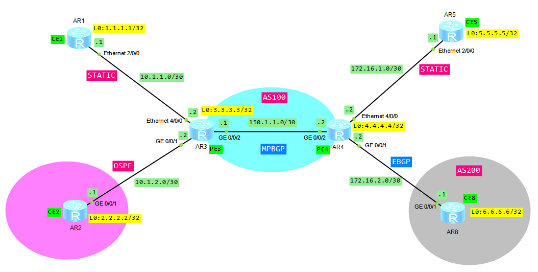
  1. CE1 and CE5 are in VPN labnario_1
  2. CE2 and CE8 are in VPN labnario_2
  3. ISIS level -2 as IGP
  4. Connections CE1—PE3 and CE5—PE4 – static routes
  5. Connection CE2—PE3 – OSPF
  6. Connection CE8—PE4 – EBGP
  7. Users in different VPNs cannot access each other.

A BGP/MPLS IP VPN uses the Border Gateway Protocol (BGP) to advertise VPN routes and the Multiprotocol Label Switching (MPLS) to forward VPN packets on backbone networks.

To exchange routes between a PE and a CE, static route, RIP multi-instance, OSPF multi-instance, ISIS multi-instance, or EBGP, can be used.

The BGP/MPLS IP VPN model consists of the following parts:

  • A Customer Edge (CE) is an edge device on the customer network, which has one or more interfaces directly connected to the service provider network. Usually, CEs do not know anything about VPNs and do not need to support MPLS.
  • A Provider Edge (PE) is an edge device on the provider network, which is directly connected to the CE. In the MPLS network, PE performs all the VPN-related processing.
  • A Provider (P) is a backbone device on the provider network, which is not directly connected to the CE. P router only needs to possess basic MPLS forwarding capabilities and does not need to maintain information about VPNs.

Based on the above topology:

  • Configure IP addresses on all routers
  • Configure an IGP on the MPLS backbone to allow the PEs to reach each other. If you want to recall how to configure ISIS go to ISIS on Huawei routers

To simplify our topology, only 2 PE routers have been used, P router is not necessary to show VPNs functionalities.

Check ISIS protocol on PE routers:

[AR3]display isis peer

                          Peer information for ISIS(1)

  System Id     Interface          Circuit Id       State HoldTime Type     PRI
-------------------------------------------------------------------------------
0040.0400.4004  GE0/0/2            0000000001        Up   29s      L2       -- 

Total Peer(s): 1

[AR3]dis ip routing-table 
Route Flags: R - relay, D - download to fib
------------------------------------------------------------------------------
Routing Tables: Public
         Destinations : 9        Routes : 9        

Destination/Mask    Proto   Pre  Cost      Flags NextHop         Interface

        3.3.3.3/32  Direct  0    0           D   127.0.0.1       LoopBack0
        4.4.4.4/32  ISIS-L2 15   10          D   150.1.1.2       GigabitEthernet0/0/2
      127.0.0.0/8   Direct  0    0           D   127.0.0.1       InLoopBack0
      127.0.0.1/32  Direct  0    0           D   127.0.0.1       InLoopBack0
127.255.255.255/32  Direct  0    0           D   127.0.0.1       InLoopBack0
      150.1.1.0/30  Direct  0    0           D   150.1.1.1       GigabitEthernet0/0/2
      150.1.1.1/32  Direct  0    0           D   127.0.0.1       GigabitEthernet0/0/2
      150.1.1.3/32  Direct  0    0           D   127.0.0.1       GigabitEthernet0/0/2
255.255.255.255/32  Direct  0    0           D   127.0.0.1       InLoopBack0

[AR4]dis isis peer

                          Peer information for ISIS(1)

  System Id     Interface          Circuit Id       State HoldTime Type     PRI
-------------------------------------------------------------------------------
0030.0300.3003  GE0/0/2            0000000001        Up   25s      L2       -- 

Total Peer(s): 1

[AR4]dis ip routing-table 
Route Flags: R - relay, D - download to fib
------------------------------------------------------------------------------
Routing Tables: Public
         Destinations : 9        Routes : 9        

Destination/Mask    Proto   Pre  Cost      Flags NextHop         Interface

        3.3.3.3/32  ISIS-L2 15   10          D   150.1.1.1       GigabitEthernet0/0/2
        4.4.4.4/32  Direct  0    0           D   127.0.0.1       LoopBack0
      127.0.0.0/8   Direct  0    0           D   127.0.0.1       InLoopBack0
      127.0.0.1/32  Direct  0    0           D   127.0.0.1       InLoopBack0
127.255.255.255/32  Direct  0    0           D   127.0.0.1       InLoopBack0
      150.1.1.0/30  Direct  0    0           D   150.1.1.2       GigabitEthernet0/0/2
      150.1.1.2/32  Direct  0    0           D   127.0.0.1       GigabitEthernet0/0/2
      150.1.1.3/32  Direct  0    0           D   127.0.0.1       GigabitEthernet0/0/2
255.255.255.255/32  Direct  0    0           D   127.0.0.1       InLoopBack0

Configure basic MPLS capabilities and MPLS LDP on the MPLS backbone network to set up the LDP LSP.

Configure PE3:

[AR3]mpls lsr-id 3.3.3.3
[AR3]mpls
[AR3-mpls]quit
[AR3]mpls ldp
[AR3-mpls-ldp]quit
[AR3]int GigabitEthernet 0/0/2
[AR3-GigabitEthernet0/0/2]mpls
[AR3-GigabitEthernet0/0/2]mpls ldp

Configure PE4:

[AR4]mpls lsr-id 4.4.4.4
[AR4]mpls
[AR4-mpls]quit
[AR4]mpls ldp
[AR4-mpls-ldp]quit	
[AR4]interface gig 0/0/2
[AR4-GigabitEthernet0/0/2]mpls
[AR4-GigabitEthernet0/0/2]mpls ldp

Let’s check if MPLS LDP has been set up:

[AR3]dis mpls ldp peer

 LDP Peer Information in Public network
 A '*' before a peer means the peer is being deleted.
 ------------------------------------------------------------------------------
 PeerID                 TransportAddress   DiscoverySource
 ------------------------------------------------------------------------------
 4.4.4.4:0              4.4.4.4            GigabitEthernet0/0/2
 ------------------------------------------------------------------------------
 TOTAL: 1 Peer(s) Found.

[AR3]dis mpls ldp session 

 LDP Session(s) in Public Network
 Codes: LAM(Label Advertisement Mode), SsnAge Unit(DDDD:HH:MM)
 A '*' before a session means the session is being deleted.
 ------------------------------------------------------------------------------
 PeerID             Status      LAM  SsnRole  SsnAge      KASent/Rcv
 ------------------------------------------------------------------------------
 4.4.4.4:0          Operational DU   Passive  0000:00:11  45/45
 ------------------------------------------------------------------------------
 TOTAL: 1 session(s) Found.

[AR3]dis mpls ldp lsp

 LDP LSP Information
 -------------------------------------------------------------------------------
 DestAddress/Mask   In/OutLabel    UpstreamPeer    NextHop         OutInterface
 -------------------------------------------------------------------------------
 3.3.3.3/32         3/NULL         4.4.4.4         127.0.0.1       InLoop0
*3.3.3.3/32         Liberal/1024                   DS/4.4.4.4
 4.4.4.4/32         NULL/3         -               150.1.1.2       GE0/0/2
 4.4.4.4/32         1024/3         4.4.4.4         150.1.1.2       GE0/0/2
 -------------------------------------------------------------------------------
 TOTAL: 3 Normal LSP(s) Found.
 TOTAL: 1 Liberal LSP(s) Found.
 TOTAL: 0 Frr LSP(s) Found.
 A '*' before an LSP means the LSP is not established
 A '*' before a Label means the USCB or DSCB is stale
 A '*' before a UpstreamPeer means the session is stale
 A '*' before a DS means the session is stale
 A '*' before a NextHop means the LSP is FRR LSP

Establish the MP-IBGP peer relationship between the PEs.

PE3:

[AR3]bgp 100
[AR3-bgp]peer 4.4.4.4 as-number 100
[AR3-bgp]peer 4.4.4.4 connect-interface LoopBack0
[AR3-bgp]ipv4-family vpnv4
[AR3-bgp-af-vpnv4]peer 4.4.4.4 enable
[AR3-bgp-af-vpnv4]quit
[AR3-bgp]dis this
#
bgp 100
 peer 4.4.4.4 as-number 100 
 peer 4.4.4.4 connect-interface LoopBack0
 #
 ipv4-family unicast
  undo synchronization
  peer 4.4.4.4 enable
 # 
 ipv4-family vpnv4
  policy vpn-target
  peer 4.4.4.4 enable

As we use only MP-BGP, we can disable unicast BGP peer:

[AR3-bgp]ipv4-family unicast
[AR3-bgp-af-ipv4]undo peer 4.4.4.4 enable

Configuration of PE4 is similar and it is omitted here.

As you can see only MP-BGP has been established:

[AR3]dis bgp peer

[AR3]dis bgp vpnv4 all peer

 BGP local router ID : 3.3.3.3
 Local AS number : 100
 Total number of peers : 1		  Peers in established state : 1

  Peer            V          AS  MsgRcvd  MsgSent  OutQ  Up/Down       State PrefRcv

  4.4.4.4         4         100       24       24     0 00:18:21 Established       4

Configure VPN instances (VRFs) on both PE routers:

[AR3]dis cur config vpn
#
ip vpn-instance labnario_1
 ipv4-family
  route-distinguisher 100:1
  vpn-target 100:1 export-extcommunity
  vpn-target 100:1 import-extcommunity
#
ip vpn-instance labnario_2
 ipv4-family
  route-distinguisher 100:2
  vpn-target 100:2 export-extcommunity
  vpn-target 100:2 import-extcommunity

[AR4]dis cur config vpn
#
ip vpn-instance labnario_1
 ipv4-family
  route-distinguisher 100:1
  vpn-target 100:1 export-extcommunity
  vpn-target 100:1 import-extcommunity
#
ip vpn-instance labnario_2
 ipv4-family
  route-distinguisher 100:2
  vpn-target 100:2 export-extcommunity
  vpn-target 100:2 import-extcommunity

Route distinguisher RD is used to distinguish the IPv4 prefixes with the same address space. Address spaces of different VPNs may overlap.

The VPN target is a 32-bit BGP extension community attribute. BGP/MPLS IP VPN uses the VPN target to control the advertisement of VPN routing information.

  • Export target: After learning the IPv4 routes from directly connected sites, a local PE converts the routes to VPN-IPv4 routes and sets the export target attribute for those routes. As the BGP extension community attribute, the export target attribute is advertised with the routes.
  • Import target: After receiving VPN-IPv4 routes from other PEs, a PE checks the export target attribute of the routes. If the export target is identical with the import target of a VPN instance on the PE, the PE adds the route to the VPN routing table.

Bind the instances to the CE interfaces on both PEs. Remember that all IP related configuration will be removed from the interfaces:

[AR4-Ethernet4/0/0]ip binding vpn-instance labnario_1
Info: All IPv4 related configurations on this interface are removed!
Info: All IPv6 related configurations on this interface are removed!
[AR4-Ethernet4/0/0]
[AR4-Ethernet4/0/0]ip address 172.16.1.2 255.255.255.252

[AR4-GigabitEthernet0/0/1]ip binding vpn-instance labnario_2
Info: All IPv4 related configurations on this interface are removed!
Info: All IPv6 related configurations on this interface are removed!
[AR4-GigabitEthernet0/0/1]
[AR4-GigabitEthernet0/0/1]
[AR4-GigabitEthernet0/0/1]ip address 172.16.2.2 255.255.255.252

Configure static route to Loopback 0 interfaces of CE1 and CE5 (from PE3 and PE4 respectively):

[AR3]ip route-static vpn-instance labnario_1 1.1.1.1 255.255.255.255 10.1.1.1

[AR4]ip route-static vpn-instance labnario_1 5.5.5.5 255.255.255.255 172.16.1.1

Go to BGP VPN instance IPv4 address family of PE routers and import direct and static routes into BGP:

[AR3]bgp 100
[AR3-bgp]ipv4-family vpn-instance labnario_1
[AR3-bgp-labnario_1]import-route direct 
[AR3-bgp-labnario_1]import-route static 

[AR4]bgp 100
[AR4-bgp]ipv4-family vpn-instance labnario_1
[AR4-bgp-labnario_1]import-route direct 
[AR4-bgp-labnario_1]import-route static

Configure default routing on CE1 and CE5:

[AR1]ip route-static 0.0.0.0 0.0.0.0 10.1.1.2
[AR5]ip route-static 0.0.0.0 0.0.0.0 172.16.1.2

Configure OSPF between PE3 and CE2:

PE3:

[AR3]dis cur config ospf
#
ospf 1 vpn-instance labnario_2
area 0.0.0.0 
  network 10.1.2.0 0.0.0.3

CE2:

[AR2]dis cur config ospf
#
ospf 1 
 area 0.0.0.0 
  network 2.2.2.2 0.0.0.0 
  network 10.1.2.0 0.0.0.3

Check OSPF peering:

[AR3]dis ospf peer

	 OSPF Process 1 with Router ID 10.1.2.2
		 Neighbors 

 Area 0.0.0.0 interface 10.1.2.2(GigabitEthernet0/0/1)'s neighbors
 Router ID: 10.1.2.1         Address: 10.1.2.1        
   State: Full  Mode:Nbr is  Slave  Priority: 1
   DR: 10.1.2.2  BDR: 10.1.2.1  MTU: 0    
   Dead timer due in 38  sec 
   Retrans timer interval: 5 
   Neighbor is up for 00:47:33     
   Authentication Sequence: [ 0 ]

Import OSPF into BGP vpn-instance labnario_2:

[AR3]bgp 100
[AR3-bgp]ipv4-family vpn-instance labnario_2
[AR3-bgp-labnario_2]import-route ospf 1

Import BGP into OSPF:

[AR3]ospf vpn-instance labnario_2
[AR3-ospf-1]import-route bgp

Configure external BGP EBGP peering between PE4 and CE8:

CE8:

[AR8]dis cur config bgp
#
bgp 200
 peer 172.16.2.2 as-number 100 
 #
 ipv4-family unicast
  undo synchronization
  import-route direct
  peer 172.16.2.2 enable

PE4:

[AR4]bgp 100
[AR4-bgp]ipv4-family vpn-instance labnario_2
[AR4-bgp-labnario_2]peer 172.16.2.1 as-number 200
[AR4-bgp-labnario_2]import-route direct

Display BGP peers:

[AR4]dis bgp vpnv4 all peer

 BGP local router ID : 4.4.4.4
 Local AS number : 100
 Total number of peers : 2		  Peers in established state : 2

  Peer            V          AS  MsgRcvd  MsgSent  OutQ  Up/Down       State PrefRcv

  3.3.3.3         4         100       10       11     0 00:04:52 Established       4

  Peer of IPv4-family for vpn instance :

 VPN-Instance labnario_2, Router ID 4.4.4.4:
  172.16.2.1      4         200        9       10     0 00:05:04 Established       2

Let’s check VRF routing tables on both PEs:

[AR3]dis ip rout vpn-instance labnario_1
Route Flags: R - relay, D - download to fib
------------------------------------------------------------------------------
Routing Tables: labnario_1
         Destinations : 7        Routes : 7        

Destination/Mask    Proto   Pre  Cost      Flags NextHop         Interface

        1.1.1.1/32  Static  60   0          RD   10.1.1.1        Ethernet4/0/0
        5.5.5.5/32  IBGP    255  0          RD   4.4.4.4         GigabitEthernet0/0/2
       10.1.1.0/30  Direct  0    0           D   10.1.1.2        Ethernet4/0/0
       10.1.1.2/32  Direct  0    0           D   127.0.0.1       Ethernet4/0/0
       10.1.1.3/32  Direct  0    0           D   127.0.0.1       Ethernet4/0/0
     172.16.1.0/30  IBGP    255  0          RD   4.4.4.4         GigabitEthernet0/0/2
255.255.255.255/32  Direct  0    0           D   127.0.0.1       InLoopBack0

[AR3]dis ip rout vpn-instance labnario_2
Route Flags: R - relay, D - download to fib
------------------------------------------------------------------------------
Routing Tables: labnario_2
         Destinations : 7        Routes : 7        

Destination/Mask    Proto   Pre  Cost      Flags NextHop         Interface

        2.2.2.2/32  OSPF    10   1           D   10.1.2.1        GigabitEthernet0/0/1
        6.6.6.6/32  IBGP    255  0          RD   4.4.4.4         GigabitEthernet0/0/2
       10.1.2.0/30  Direct  0    0           D   10.1.2.2        GigabitEthernet0/0/1
       10.1.2.2/32  Direct  0    0           D   127.0.0.1       GigabitEthernet0/0/1
       10.1.2.3/32  Direct  0    0           D   127.0.0.1       GigabitEthernet0/0/1
     172.16.2.0/30  IBGP    255  0          RD   4.4.4.4         GigabitEthernet0/0/2
255.255.255.255/32  Direct  0    0           D   127.0.0.1       InLoopBack0

[AR4]dis ip routing-table vpn-instance labnario_1
Route Flags: R - relay, D - download to fib
------------------------------------------------------------------------------
Routing Tables: labnario_1
         Destinations : 7        Routes : 7        

Destination/Mask    Proto   Pre  Cost      Flags NextHop         Interface

        1.1.1.1/32  IBGP    255  0          RD   3.3.3.3         GigabitEthernet0/0/2
        5.5.5.5/32  Static  60   0          RD   172.16.1.1      Ethernet4/0/0
       10.1.1.0/30  IBGP    255  0          RD   3.3.3.3         GigabitEthernet0/0/2
     172.16.1.0/30  Direct  0    0           D   172.16.1.2      Ethernet4/0/0
     172.16.1.2/32  Direct  0    0           D   127.0.0.1       Ethernet4/0/0
     172.16.1.3/32  Direct  0    0           D   127.0.0.1       Ethernet4/0/0
255.255.255.255/32  Direct  0    0           D   127.0.0.1       InLoopBack0

[AR4]dis ip routing-table vpn-instance labnario_2
Route Flags: R - relay, D - download to fib
------------------------------------------------------------------------------
Routing Tables: labnario_2
         Destinations : 7        Routes : 7        

Destination/Mask    Proto   Pre  Cost      Flags NextHop         Interface

        2.2.2.2/32  IBGP    255  2          RD   3.3.3.3         GigabitEthernet0/0/2
        6.6.6.6/32  EBGP    255  0           D   172.16.2.1      GigabitEthernet0/0/1
       10.1.2.0/30  IBGP    255  0          RD   3.3.3.3         GigabitEthernet0/0/2
     172.16.2.0/30  Direct  0    0           D   172.16.2.2      GigabitEthernet0/0/1
     172.16.2.2/32  Direct  0    0           D   127.0.0.1       GigabitEthernet0/0/1
     172.16.2.3/32  Direct  0    0           D   127.0.0.1       GigabitEthernet0/0/1
255.255.255.255/32  Direct  0    0           D   127.0.0.1       InLoopBack0

Check connectivity in both VPNs:

[AR3]ping -vpn-instance labnario_1 5.5.5.5
  PING 5.5.5.5: 56  data bytes, press CTRL_C to break
    Reply from 5.5.5.5: bytes=56 Sequence=1 ttl=254 time=360 ms
    Reply from 5.5.5.5: bytes=56 Sequence=2 ttl=254 time=170 ms
    Reply from 5.5.5.5: bytes=56 Sequence=3 ttl=254 time=120 ms
    Reply from 5.5.5.5: bytes=56 Sequence=4 ttl=254 time=90 ms
    Reply from 5.5.5.5: bytes=56 Sequence=5 ttl=254 time=70 ms

  --- 5.5.5.5 ping statistics ---
    5 packet(s) transmitted
    5 packet(s) received
    0.00% packet loss
    round-trip min/avg/max = 70/162/360 ms

[AR3]ping -vpn-instance labnario_2 6.6.6.6
  PING 6.6.6.6: 56  data bytes, press CTRL_C to break
    Reply from 6.6.6.6: bytes=56 Sequence=1 ttl=254 time=130 ms
    Reply from 6.6.6.6: bytes=56 Sequence=2 ttl=254 time=130 ms
    Reply from 6.6.6.6: bytes=56 Sequence=3 ttl=254 time=80 ms
    Reply from 6.6.6.6: bytes=56 Sequence=4 ttl=254 time=100 ms
    Reply from 6.6.6.6: bytes=56 Sequence=5 ttl=254 time=60 ms

  --- 6.6.6.6 ping statistics ---
    5 packet(s) transmitted
    5 packet(s) received
    0.00% packet loss
    round-trip min/avg/max = 60/100/130 ms

Ping from CE1 to CE5:

[AR1]ping 5.5.5.5
  PING 5.5.5.5: 56  data bytes, press CTRL_C to break
    Reply from 5.5.5.5: bytes=56 Sequence=1 ttl=253 time=220 ms
    Reply from 5.5.5.5: bytes=56 Sequence=2 ttl=253 time=100 ms
    Reply from 5.5.5.5: bytes=56 Sequence=3 ttl=253 time=80 ms
    Reply from 5.5.5.5: bytes=56 Sequence=4 ttl=253 time=90 ms
    Reply from 5.5.5.5: bytes=56 Sequence=5 ttl=253 time=90 ms

  --- 5.5.5.5 ping statistics ---
    5 packet(s) transmitted
    5 packet(s) received
    0.00% packet loss
    round-trip min/avg/max = 80/116/220 ms

Ping from CE2 to CE8:

[AR2]ping 6.6.6.6
  PING 6.6.6.6: 56  data bytes, press CTRL_C to break
    Reply from 6.6.6.6: bytes=56 Sequence=1 ttl=253 time=210 ms
    Reply from 6.6.6.6: bytes=56 Sequence=2 ttl=253 time=80 ms
    Reply from 6.6.6.6: bytes=56 Sequence=3 ttl=253 time=200 ms
    Reply from 6.6.6.6: bytes=56 Sequence=4 ttl=253 time=70 ms
    Reply from 6.6.6.6: bytes=56 Sequence=5 ttl=253 time=70 ms

  --- 6.6.6.6 ping statistics ---
    5 packet(s) transmitted
    5 packet(s) received
    0.00% packet loss
    round-trip min/avg/max = 70/126/210 ms

Ping from CE1 to CE8:

[AR1]ping 6.6.6.6
  PING 6.6.6.6: 56  data bytes, press CTRL_C to break
    Request time out
    Request time out
    Request time out
    Request time out
    Request time out

  --- 6.6.6.6 ping statistics ---
    5 packet(s) transmitted
    0 packet(s) received
    100.00% packet loss

As we can see, users in different VPNs cannot access each other.

Read More »

error-down auto-recovery on Huawei switches

Some of you may know Cisco’s err-disable recovery feature, which allows to automatically bring a port from err-disable back to UP state. Huawei switches have similar functionality, which is called error-down auto-recovery.

There are five reasons a port can enter into error-down state:

  • BPDU protection
  • EFM threshold
  • EFM remote failure
  • Auto defend
  • Link flapping
  • MAC address flapping

Let’s take a look, how this feature works, in a network running STP, when BPDU protection is the reason that a port goes into DOWN state. If you are not familiar with BPDU protection feature, read my previous article “Protecting STP on Huawei switches”.

I have configured STP BPDU protection on the Ethernet 0/0/1 interface of labnarioSW1 switch as follows:

[labnarioSW1]int e0/0/1
[labnarioSW1-Ethernet0/0/1]stp edged-port enable
[labnarioSW1]stp bpdu-protection

Error-down auto-recovery feature has been enabled on the switch using command:

[labnarioSW1]error-down auto-recovery cause bpdu-protection interval 30

Option “interval” specifies how long (in seconds) our interface will be in DOWN state before it transitions to UP state. Any integer ranging from 30 to 86400 can be chosen.

On the other end of this Ethernet link labnarioSW2 switch is connected, to simulate STP attack. STP is temporary disabled on the Ethernet 0/0/1 port of the labnarioSW2, to prevent the Ethernet 0/0/1 port of the labnarioSW1 switch from transition to DOWN state.

The only role of the labnarioSW2 switch is to generate BPDU frames. Any other device, which can send STP BPDU frames, can be connected as well. So let’s start sending STP BPDUs:

[labnarioSW2-Ethernet0/0/1]stp enable

Please see log messages, generated by the BPDU protection and error-down auto-recovery feature, enabled on labnarioSW1 switch:

[labnarioSW1]
May 23 2013 21:30:34-08:00 labnarioSW1 %%01MSTP/4/BPDU_PROTECTION(l)[62]:This edged-port Ethernet0/0/1 that enabled BPDU-Protection will be shutdown, because it received BPDU packet!
May 23 2013 21:30:34-08:00 labnarioSW1 %%01ERRDOWN/4/ERRDOWN_DOWNNOTIFY(l)[63]:Notify interface to change status to error-down. (InterfaceName=Ethernet0/0/1, Cause=bpdu-protection)
May 23 2013 21:30:34-08:00 labnarioSW1 ERRDOWN/4/ErrordownOccur:OID 1.3.6.1.4.1.2011.5.25.257.2.1 Error-down occured. (Ifindex=6, Ifname=Ethernet0/0/1, Cause=bpdu-protection)
May 23 2013 21:30:34-08:00 labnarioSW1 %%01PHY/1/PHY(l)[64]: Ethernet0/0/1: change status to down

To display the status of the error-down auto-recovery, use the command:

[labnarioSW1]display error-down recovery int e0/0/1
  interface                      error-down cause          recovery   remainder time(sec) 
  ------------------------------------------------------------------------------
  Ethernet0/0/1                  bpdu-protection           30         17        

[labnarioSW1]display error-down recovery int e0/0/1
  interface                      error-down cause          recovery   remainder time(sec) 
  ------------------------------------------------------------------------------
  Ethernet0/0/1                  bpdu-protection           30         8         

[labnarioSW1]display error-down recovery int e0/0/1
  interface                      error-down cause          recovery   remainder time(sec)
  ------------------------------------------------------------------------------
  Ethernet0/0/1                  bpdu-protection           30         3

After 30 seconds, error-down auto-recovery feature transitions  port back to UP state:

May 23 2013 21:31:03-08:00 labnarioSW1 %%01ERRDOWN/4/ERRDOWN_DOWNRECOVER(l)[67]:Notify interface to recover state from error-down. (InterfaceName=Ethernet0/0/1) May 23 2013 21:31:03-08:00 labnarioSW1 ERRDOWN/4/ErrordownRecover:OID 1.3.6.1.4.1.2011.5.25.257.2.2 Error-down recovered. (Ifindex=6, Ifname=Ethernet0/0/1, Cause=bpdu-protection, RecoverType=auto recovery) May 23 2013 21:31:05-08:00 labnarioSW1 %%01PHY/1/PHY(l)[68]: Ethernet0/0/1: change status to up

Read More »

ISIS DIS election

Let’s check today how a Designated Intermediate System (DIS) is elected in broadcast network.

Unlike in OSPF, in ISIS, routers of the same level, in a network segment, set up adjacencies (including non-DIS routers). DIS, as a pseudo node also generates LSPs, to describe available routers in the network. A pseudo node is indentified by the system ID of the DIS and the 1-byte circuit ID, which is always not 0. The main task of DIS is to reduce the number of generated LSPs. Even though all routers set up adjacencies in an ISIS broadcast network, LSDBs are synchronized by the DISs. One router can be DIS either for Level -1 or Level 2 routers. It depends on DIS priority configured. You can configure different DIS priority for different levels. The highest priority means the router is elected as DIS. In case that all routers have the same DIS priority, the one with the highest MAC address is chosen as DIS. By default DIS priority is set to 64 and can be changed manually. Comparing to OSFP DR, the router with the priority 0 also takes part in DIS election. Each time you connect a new router with higher DIS priority, the new router is elected as the new DIS, which causes LSPs flooding.

Let’s leave theory and carry out a test of DIS election in ISIS broadcast network.

Based on the below topology configure, IP addresses for physical and loopback interfaces (it is omitted here).

Configure ISIS protocol on all routers. How to do this? Go to ISIS on Huawei routers.

You can add ISIS name for each router to simplify maintenance and troubleshooting (AR1 as an example):

[AR1]isis	
[AR1-isis-1]is-name AR1

Check ARP table for AR1 router to find out which router has the highest MAC address:

[AR1]dis arp int eth 4/0/0
IP ADDRESS      MAC ADDRESS     EXPIRE(M) TYPE        INTERFACE   VPN-INSTANCE 
                                          VLAN/CEVLAN PVC                      
------------------------------------------------------------------------------
10.10.10.1      00e0-fc0d-7860            I -         Eth4/0/0
10.10.10.3      00e0-fc0d-e793  19        D-0         Eth4/0/0
10.10.10.4      00e0-fc06-db85  19        D-0         Eth4/0/0
10.10.10.2      00e0-fc0d-27df  19        D-0         Eth4/0/0
------------------------------------------------------------------------------
Total:4         Dynamic:3       Static:0     Interface:1

As we can see from the output, AR3 router’s MAC address 00e0-fc0d-e793 is the highest and will be elected as DIS. Why? Because DIS priority of all routers is set as defualt 64. Let’s check it:

[AR1]display isis peer

                          Peer information for ISIS(1)

  System Id     Interface          Circuit Id       State HoldTime Type     PRI
-------------------------------------------------------------------------------
AR3             Eth4/0/0           AR3.01            Up   7s       L1(L1L2) 64 
AR4             Eth4/0/0           AR3.01            Up   28s      L1(L1L2) 64 
AR2             Eth4/0/0           AR3.01            Up   29s      L1(L1L2) 64 
AR3             Eth4/0/0           AR3.01            Up   8s       L2(L1L2) 64 
AR4             Eth4/0/0           AR3.01            Up   23s      L2(L1L2) 64 
AR2             Eth4/0/0           AR3.01            Up   28s      L2(L1L2) 64 

Total Peer(s): 6

[AR1]display isis interface 

                       Interface information for ISIS(1)
                       ---------------------------------
 Interface       Id      IPV4.State          IPV6.State      MTU  Type  DIS   
 Loop0           001         Up                 Down         1500 L1/L2 -- 
 Eth4/0/0        001         Up                 Down         1497 L1/L2 No/No 

[AR2]display isis interface 

                       Interface information for ISIS(1)
                       ---------------------------------
 Interface       Id      IPV4.State          IPV6.State      MTU  Type  DIS   
 Loop0           001         Up                 Down         1500 L1/L2 -- 
 Eth4/0/0        001         Up                 Down         1497 L1/L2 No/No 

[AR3]display isis interface 

                       Interface information for ISIS(1)
                       ---------------------------------
 Interface       Id      IPV4.State          IPV6.State      MTU  Type  DIS   
 Loop0           001         Up                 Down         1500 L1/L2 -- 
 Eth4/0/0        001         Up                 Down         1497 L1/L2 Yes/Yes

[AR4]display isis interface 

                       Interface information for ISIS(1)
                       ---------------------------------
 Interface       Id      IPV4.State          IPV6.State      MTU  Type  DIS   
 Loop0           001         Up                 Down         1500 L1/L2 -- 
 Eth2/0/0        001         Up                 Down         1497 L1/L2 No/No

AR3.01 – As it was mentioned earlier, a pseudo node is indentified by the system ID of the DIS and the 1-byte circuit ID, which is always not 0.

And now change DIS priority of AR1 to 100:

[AR1]int Ethernet 4/0/0
[AR1-Ethernet4/0/0]isis dis-priority 100 (Level-1-2 by default)

Let’s check what’s happend:

[AR1]dis isis interface 

                       Interface information for ISIS(1)
                       ---------------------------------
 Interface       Id      IPV4.State          IPV6.State      MTU  Type  DIS   
 Loop0           001         Up                 Down         1500 L1/L2 -- 
 Eth4/0/0        001         Up                 Down         1497 L1/L2 Yes/Yes

Now router AR1 has been chosen as DIS. As you can see, it is the DIS for both levels because all routers in our topology are Level-1-2 routers. You can test the same for hierarchical topology, changing circuit-type of some routers to Level-1 and Level-2. You can also change DIS priority for Level-1 or Level-2.

Read More »

protecting STP on Huawei switches

As a continuation of the STP Root Protection feature I want to describe additional STP protection functions and show you, where these functions should be implemented, in a typical campus LAN environment.

BPDU Protection feature can be used to protect switches against STP BPDU attacks. It should be implemented on every switch, which has ports directly connected to end-user workstations. This is because we do not expect receiving STP BPDU from user workstations. When STP BPDUs are received on the edge port, STP topology recalculation occurs, causing network flapping. If the port is configured with BPDU Protection and the switching device receives STP BPDUs, then the port is placed into shutdown state, protecting STP topology from recalculation. By default BPDU Protection feature is disabled on Huawei switches. To enable it:

<labnario_sw>system-view 
[labnario_sw]interface Ethernet 0/0/1
[labnario_sw-Ethernet0/0/1]stp edged-port enable 
[labnario_sw-Ethernet0/0/1]quit
[labnario_sw]stp bpdu-protection

When a switch port is configured as a STP Edged and STP BPDU is received, the port is placed into shutdown state:

May 13 2013 20:17:00-08:00 labnario_sw%%01MSTP/4/BPDU_PROTECTION(l)[4]:This edged-port Ethernet0/0/1 that enabled BPDU-Protection will be shutdown, because it received BPDU packet!
[labnario_sw-Ethernet0/0/1]dis cur int e0/0/1
#
interface Ethernet0/0/1
 shutdown
 stp edged-port enable

[labnario_sw-Ethernet0/0/1]dis int eth0/0/1
Ethernet0/0/1 current state : Administratively DOWN
Line protocol current state : DOWN

To bring the port back to UP state, manual port reconfiguration is required or auto recovery feature should be enabled on the switch.

TC Protection (TC – Topology Change) feature is used to suppress TC BPDUs (BPDU frames advertising STP topology change). When a switch receives a large number of TC BPDUs in a short time period, it has to frequently process MAC and ARP table entries, which can lead to CPU resources exhausting. To prevent this from happening, TC Protection can be configured, so that the switch will process TC BPDUs only with the given number of times within a specified time period. To enable TC Protection and change its default settings:

[labnario_sw]stp tc-protection
[labnario_sw]stp tc-protection threshold ?
  INTEGER  The threshold of TC-BPDU protection, default is 1

[labnario_sw]stp tc-protection threshold 3

The default threshold is 1, the time is specified by the STP Hello timer, which equals to 2 seconds, and can be easy changed using command:

[labnario_sw]stp timer hello ?
  INTEGER  Hello time in centiseconds, in steps of 100, the default value is 200

When the number of TC BPDUs, received by the switch, exceeds the specified threshold in a given time period, switch processes the excess TC BPDUs, after the specified time period expires. TC Protection feature should be enabled on every switch in a LAN environment.

Loop Protection feature provides additional protection against L2 forwarding loops. STP relies on a continuous reception or transmission of BPDUs based on the port role. The designated port transmits BPDUs and the non-designated port (ROOT, ALTERNATE) receives BPDUs. An STP loop is created, when one of the ports, of a physically redundant topology, no longer receives STP BPDUs. This usually happens, when ALTERNATE port in DISCARDING state stops receiving STP PBDUs, and as a result, moves to a Designated role and FORWARDING state. It means that there is no longer blocking port in redundant physical topology and loop is created. Loop protection feature, enabled on the interface, moves this port into Designated role and DISCARDING state, when no STP BPDUs are received in a prescriptive time. Loop Protection feature should be enabled on ROOT and ALTERNATE ports for every possible STP topology including failover scenarios.

Look at the following example to see Loop Protection feature in action:

[labnario_sw]dis cur | beg t0/0/1
#
interface GigabitEthernet0/0/1
 stp loop-protection
#
interface GigabitEthernet0/0/2
 stp loop-protection
#
[labnario_sw]dis stp brie
 MSTID  Port                        Role  STP State     Protection
   0    GigabitEthernet0/0/1        ALTE  DISCARDING      LOOP
   0    GigabitEthernet0/0/2        ROOT  FORWARDING      LOOP
May 14 2013 13:50:06-08:00 Huawei %%01MSTP/4/LOOP_GUARD(l)[2]:MSTP process 0 Instance0's LOOP-Protection port GigabitEthernet0/0/1 did not receive message in prescriptive time!
[labnario_sw]dis stp brie
 MSTID  Port                        Role  STP State     Protection
   0    GigabitEthernet0/0/1        DESI  DISCARDING      LOOP
   0    GigabitEthernet0/0/2        ROOT  FORWARDING      LOOP

Recovery is automatic when port starts receiving STP BPDUs, no additional administrative intervention is required. By default Loop Protection feature is disabled on Huawei switches.


Read More »

Huawei eNSP – news

Based on the release notes of eNSP:

New features:

  • supports TAB key switch when filling IP address of SimPC
  • provides one key register function of AR_Base.

Modified features:

  • improves the stability when starting AR
  • reduces memory usage of AR
  • fixes distribution service for AR
  • fixes the dysfunction of MPLS L3VPN.

A new Huawei Enterprise Network Simulation Platform has been released.

Download, test and enjoy!

Read More »