Do you know the Private VLAN feature from Cisco switches? The same feature exists on Huawei switches and is called the MUX VLAN.
How does this feature work?
MUX VLAN allows isolating Layer2 traffic of different interfaces in the same VLAN, and still allowing access to common resources.
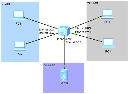
Look at the topology below. Let’s assume that we want to configure our labnariosw switch, so that:
- hosts in VLAN10 should be able to ping each other and ping server in VLAN30
- hosts in VLAN20 should be able to ping server in VLAN30 but not each other
- hosts in VLAN10 should not be able to ping hosts in VLAN20.
To do so, we need to define:
- VLAN30 as a “principal VLAN” and add interface connecting server to this VLAN
- VLAN10 as a “seprate VLAN” and add user interfaces to it
- VLAN20 as a “group VLAN” and add user interfaces to this VLAN.
Let’s start configuring our topology. As the first step VLANs 10, 20 and 30 should be configured:
<labnariosw>sys
Enter system view, return user view with Ctrl+Z.
[labnariosw]vlan batch 10 20 30
Info: This operation may take a few seconds. Please wait for a moment...done.
VLAN30 should be defined as a principal, VLAN 10 as a group VLAN, and 20 as a separate VLAN:
[labnariosw]vlan 30
[labnariosw-vlan30]mux-vlan
[labnariosw-vlan30]subordinate group 10
[labnariosw-vlan30]subordinate separate 20
As the last step, switch ports have to be added to the appropriate VLAN and MUX VLAN feature have to be enabled as follows:
[labnariosw]interface Ethernet0/0/1
[labnariosw-Ethernet0/0/1]port link-type access
[labnariosw-Ethernet0/0/1]port default vlan 10
[labnariosw-Ethernet0/0/1]port mux-vlan enable
[labnariosw]interface Ethernet0/0/2
[labnariosw-Ethernet0/0/1]port link-type access
[labnariosw-Ethernet0/0/1]port default vlan 10
[labnariosw-Ethernet0/0/1]port mux-vlan enable
[labnariosw]interface Ethernet0/0/3
[labnariosw-Ethernet0/0/1]port link-type access
[labnariosw-Ethernet0/0/1]port default vlan 20
[labnariosw-Ethernet0/0/1]port mux-vlan enable
[labnariosw]interface Ethernet0/0/4
[labnariosw-Ethernet0/0/1]port link-type access
[labnariosw-Ethernet0/0/1]port default vlan 20
[labnariosw-Ethernet0/0/1]port mux-vlan enable
[labnariosw]interface Ethernet0/0/5
[labnariosw-Ethernet0/0/1]port link-type access
[labnariosw-Ethernet0/0/1]port default vlan 30
[labnariosw-Ethernet0/0/1]port mux-vlan enable
That’s all. Some verification commands:
[labnariosw]display vlan
The total number of vlans is : 4
--------------------------------------------------------------------------------

U: Up;         D: Down;         TG: Tagged;         UT: Untagged;
MP: Vlan-mapping;               ST: Vlan-stacking;
#: ProtocolTransparent-vlan;    *: Management-vlan;
--------------------------------------------------------------------------------

VID  Type    Ports
--------------------------------------------------------------------------------
1    common  UT:Eth0/0/6(D)     Eth0/0/7(D)     Eth0/0/8(D)     Eth0/0/9(D)
                Eth0/0/10(D)    Eth0/0/11(D)    Eth0/0/12(D)    Eth0/0/13(D)
                Eth0/0/14(D)    Eth0/0/15(D)    Eth0/0/16(D)    Eth0/0/17(D)
                Eth0/0/18(D)    Eth0/0/19(D)    Eth0/0/20(D)    Eth0/0/21(D)
                Eth0/0/22(D)    GE0/0/1(D)      GE0/0/2(D)
10   mux-sub UT:Eth0/0/1(U)     Eth0/0/2(U)
20   mux-sub UT:Eth0/0/3(U)     Eth0/0/4(U)
30   mux     UT:Eth0/0/5(U)

VID  Status  Property      MAC-LRN Statistics Description
--------------------------------------------------------------------------------
1    enable  default       enable  disable    VLAN 0001
10   enable  default       enable  disable    VLAN 0010
20   enable  default       enable  disable    VLAN 0020
30   enable  default       enable  disable    VLAN 0030

[labnariosw]display mux-vlan
Principal Subordinate Type         Interface
-----------------------------------------------------------------------------
30        -           principal    Ethernet0/0/5
30        20          separate     Ethernet0/0/3 Ethernet0/0/4
30        10          group        Ethernet0/0/1 Ethernet0/0/2
-----------------------------------------------------------------------------
Now the ping test can be done to verify if our MUX VLAN configuration is working (do not forget to address your PCs).
Hosts in VLAN10 should be able to ping each other and ping server in VLAN30:
PC1>ping 192.168.100.2

Ping 192.168.100.2: 32 data bytes, Press Ctrl_C to break
From 192.168.100.2: bytes=32 seq=1 ttl=128 time=15 ms
From 192.168.100.2: bytes=32 seq=2 ttl=128 time=32 ms
From 192.168.100.2: bytes=32 seq=3 ttl=128 time=47 ms
…

PC1>ping 192.168.100.100

Ping 192.168.100.100: 32 data bytes, Press Ctrl_C to break
From 192.168.100.100: bytes=32 seq=1 ttl=128 time=15 ms
From 192.168.100.100: bytes=32 seq=2 ttl=128 time=30 ms
From 192.168.100.100: bytes=32 seq=3 ttl=128 time=16 ms
…
Hosts in VLAN20 should be able to ping server in VLAN30 but not be able to ping each other.
PC3>ping 192.168.100.100

Ping 192.168.100.100: 32 data bytes, Press Ctrl_C to break
From 192.168.100.100: bytes=32 seq=1 ttl=128 time=43 ms
From 192.168.100.100: bytes=32 seq=2 ttl=128 time=46 ms
From 192.168.100.100: bytes=32 seq=3 ttl=128 time=15 ms
…

PC4>ping 192.168.100.100

Ping 192.168.100.100: 32 data bytes, Press Ctrl_C to break
From 192.168.100.100: bytes=32 seq=1 ttl=128 time=43 ms
From 192.168.100.100: bytes=32 seq=2 ttl=128 time=46 ms
From 192.168.100.100: bytes=32 seq=3 ttl=128 time=15 ms
…

PC3>ping 192.168.100.4
Ping 192.168.100.4: 32 data bytes, Press Ctrl_C to break
    Request time out
    Request time out
    Request time out
…
Hosts in VLAN10 should not be able to ping hosts in VLAN20.
PC1>ping 192.168.100.3
Ping 192.168.100.3: 32 data bytes, Press Ctrl_C to break
    Request time out
    Request time out
    Request time out
…

PC1>ping 192.168.100.4
Ping 192.168.100.4: 32 data bytes, Press Ctrl_C to break
    Request time out
    Request time out
    Request time out
…

PC2>ping 192.168.100.3
Ping 192.168.100.3: 32 data bytes, Press Ctrl_C to break
    Request time out
    Request time out
    Request time out
…

PC2>ping 192.168.100.4
Ping 192.168.100.4: 32 data bytes, Press Ctrl_C to break
    Request time out
    Request time out
    Request time out
…
 Labnario Huawei From Scratch
