Let’s go ahead with QinQ technology. In the last post you had the opportunity to know basic QinQ tunneling on Huawei switches. The QinQ tunnel attaches the same outer tag to all the frames entering the Layer 2 QinQ interface.
In this lab I would like to attach different outer tags, to the frames entering the Layer 2 QinQ interface, according to different inner tags. It is useful when packets are going to be differentiated in a provider’s network. Why? Because of service type, user’s application etc.
In this case we have 1 enterprise network with branch office located in another city. Customer network is divided into 2 VLANs to differentiate existing services. Our task is to transparently transmit packets, through ISP network, paying attantion to not allowing traffic between VLAN10 and VLAN20.
Selective QinQ topology
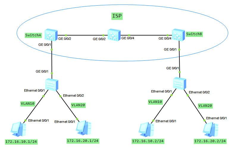
Selective QinQ configuration on Huawei switches
1. First of all, configuration of switches in HQ and branch office of the enterprise.
vlan batch 10 20
#
interface Ethernet0/0/1
 port link-type access
 port default vlan 10
#
interface Ethernet0/0/2
 port link-type access
 port default vlan 20
#
interface GigabitEthernet0/0/1
 port hybrid tagged vlan 10 20
2. Farthermore, create VLANs 100 and 200 on all ISP switches. Below SwitchA as an example.
[Switch_A]vlan batch 100 200
3. Allow VLANs 100 and 200 to be transmitted between ISP switches.
[SwitchA]interface GigabitEthernet 0/0/2
[SwitchA-GigabitEthernet0/0/2]port link-type trunk
[SwitchA-GigabitEthernet0/0/2]port trunk allow-pass vlan 100 200
[SwitchB]interface GigabitEthernet 0/0/4
[SwitchB-GigabitEthernet0/0/4]port link-type trunk
[SwitchB-GigabitEthernet0/0/4]port trunk allow-pass vlan 100 200
[ISP]interface GigabitEthernet 0/0/2
[ISP-GigabitEthernet0/0/2]port link-type trunk
[ISP-GigabitEthernet0/0/2]port trunk allow-pass vlan 100 200
[ISP]interface GigabitEthernet 0/0/4
[ISP-GigabitEthernet0/0/4]port link-type trunk
[ISP-GigabitEthernet0/0/4]port trunk allow-pass vlan 100 200
4. Configure selective QinQ on interfaces of SwitchA and SwitchB.
[Switch_A]interface GigabitEthernet 0/0/1
[Switch_A-GigabitEthernet0/0/1]qinq vlan-translation enable
[Switch_A-GigabitEthernet0/0/1] port hybrid untagged vlan 100 200
[Switch_A-GigabitEthernet0/0/1] port vlan-stacking vlan 10 stack-vlan 100
[Switch_A-GigabitEthernet0/0/1] port vlan-stacking vlan 20 stack-vlan 200
[Switch_B]interface GigabitEthernet 0/0/1
[Switch_B-GigabitEthernet0/0/1]qinq vlan-translation enable
[Switch_B-GigabitEthernet0/0/1] port hybrid untagged vlan 100 200
[Switch_B-GigabitEthernet0/0/1] port vlan-stacking vlan 10 stack-vlan 100
[Switch_B-GigabitEthernet0/0/1] port vlan-stacking vlan 20 stack-vlan 200
Please notice that selective QinQ can only be enabled on hybrid interfaces and is valid only for incoming packets. Outer VLAN tags will be removed from outgoing frames and transmitted as 802.1Q towards enterprise switches.
5. Check communication between PCs in the same VLANs.
PC_VLAN10>ping 172.16.10.2

Ping 172.16.10.2: 32 data bytes, Press Ctrl_C to break
From 172.16.10.2: bytes=32 seq=1 ttl=128 time=125 ms
From 172.16.10.2: bytes=32 seq=2 ttl=128 time=141 ms
From 172.16.10.2: bytes=32 seq=3 ttl=128 time=156 ms
From 172.16.10.2: bytes=32 seq=4 ttl=128 time=94 ms
From 172.16.10.2: bytes=32 seq=5 ttl=128 time=141 ms
PC_VLAN20>ping 172.16.20.2

Ping 172.16.20.2: 32 data bytes, Press Ctrl_C to break
From 172.16.20.2: bytes=32 seq=1 ttl=128 time=125 ms
From 172.16.20.2: bytes=32 seq=2 ttl=128 time=125 ms
From 172.16.20.2: bytes=32 seq=3 ttl=128 time=141 ms
From 172.16.20.2: bytes=32 seq=4 ttl=128 time=156 ms
From 172.16.20.2: bytes=32 seq=5 ttl=128 time=187 ms
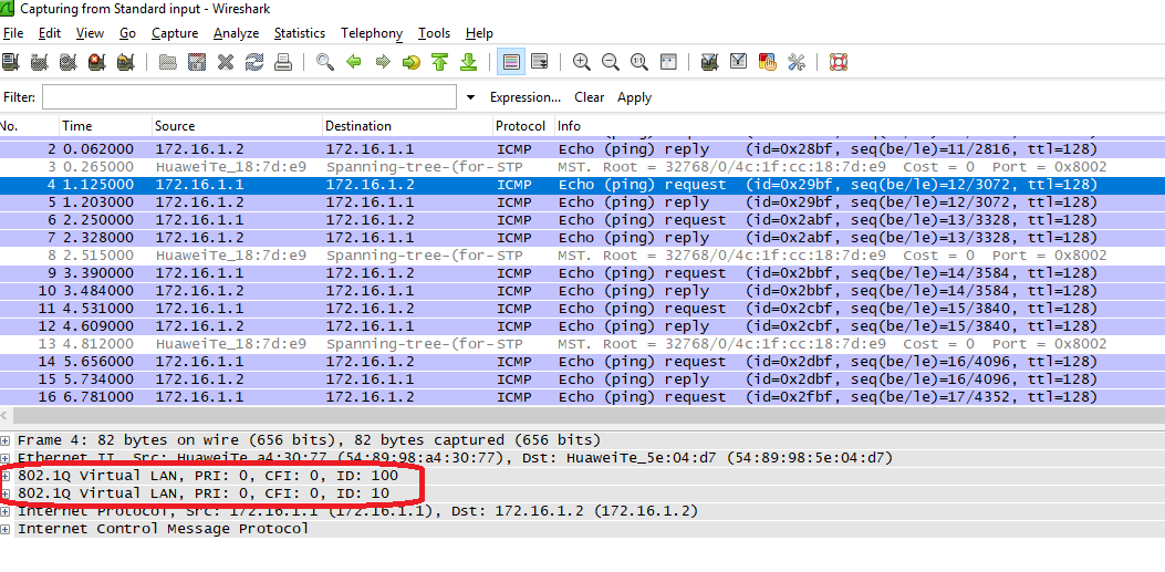
Let’s look into ICMP packet traveling through ISP network:

And finally, communication between VLANs is blocked as we assumed.
PC_VLAN10>ping 172.16.20.2

Ping 172.16.20.2: 32 data bytes, Press Ctrl_C to break
From 172.16.10.1: Destination host unreachable
Read More »