BGP stands for Border Gateway Protocol. It is widely used among Internet Service Providers to make core routing decisions on the Internet. The current BGP version is BGP-4 defined in RFC 4271.
BGP uses TCP port 179 as its underlying delivery mechanism to increase the reliability of the peer connection. BGP is called a path vector routing protocol. It uses a list of AS numbers through which the packet must pass in order to reach the destination. This list of AS numbers is associated with a BGP route and is called the AS_Path attribute. AS_Path is one of several path attributes associated with each BGP route. How does a BGP select best path to a destination network, you can read at how does BGP select routes.
I do not want to describe BGP in details, as this is out of the scope of this article. What I want to do is to show you, how to configure basic BGP features using Huawei CLI. Especially I want to show you how to:
- run BGP protocol
- configure IBGP peering sessions using peer groups
- configure EBGP peering
- advertise networks.
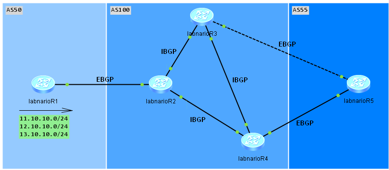
Let’s assume that we have three Autonomous Systems (see topology below):
- AS50 with only one BGP router, terminating EBGP peering with AS100
- AS100 with three routers forming IBGP full mesh using peer group
- AS55 where labnarioR5 router will form two EBGP peering sessions with AS100.
LabnarioR1 in AS50 will be advertising three prefixes, which will pass through AS100 to AS55. I want labnarioR5 router to be able to receive these three routes and reach them (be able to ping them).
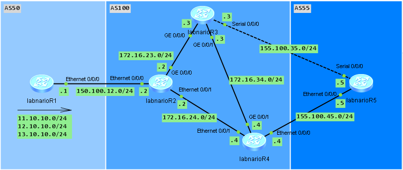
So let’s start with BGP configuration. First I want to configure labnarioR1 router to run BGP AS50 and form EBGP peering session with labnarioR2 router in AS100 (interface IP addressing configuration is omitted):
[labnarioR1]bgp 50
[labnarioR1-bgp]undo synchronization
[labnarioR1-bgp]undo summary automatic
[labnarioR1-bgp]peer 150.100.12.2 as-number 100
Now I can configure AS100. I want my three routers to form an IBGP full mesh. I will use physical interfaces to establish peering sessions for simplicity. Usually it is better to use loopback interfaces when multiple physical links exist inside AS. First I will configure EBGP session to AS50:
[labnarioR2]bgp 100
[labnarioR2-bgp]undo synchronization
[labnarioR2-bgp]undo summary automatic
[labnarioR2-bgp]peer 150.100.12.1 as-number 50
Let’s check if our EBGP session between AS50 and AS100 is established:
[labnarioR2-bgp]display bgp peer

 BGP local router ID : 150.100.12.2
 Local AS number : 100
 Total number of peers : 1		  Peers in established state : 1

  Peer            V          AS  MsgRcvd  MsgSent  OutQ  Up/Down  State    PrefRcv

  150.100.12.1    4          50       11       11     0  01:51:01 Established    0
EBGP session between AS50 and 100 is established, so I can start configuring my IBGP peering sessions in AS100. I will do that using a peer group named iBGP. Of course it is possible to specify every single peer and assign BGP specific parameters to it, but I want to use a peer group, where every BGP parameter will be assigned to it, including peering routers.
[labnarioR2-bgp]bgp 100
[labnarioR2-bgp] group iBGP internal
[labnarioR2-bgp] peer iBGP next-hop-local
[labnarioR2-bgp] peer 172.16.23.3 group iBGP
[labnarioR2-bgp] peer 172.16.24.4 group iBGP
As you see above, my iBGP peer group definition includes group type internal. When configuring peer group type internal, there is no need to assign AS number to this group. Every peer belonging to a group type internal, inherits AS number of the local AS. It is also possible to define a peer group type external. Let’s check BGP configuration on labnarioR2 router:
#
bgp 100
 peer 150.100.12.1 as-number 50
 group iBGP internal
 peer 172.16.23.3 as-number 100
 peer 172.16.23.3 group iBGP
 peer 172.16.24.4 as-number 100
 peer 172.16.24.4 group iBGP
 #
 ipv4-family unicast
  undo synchronization
  peer 150.100.12.1 enable
  peer iBGP enable
  peer iBGP next-hop-local
  peer 172.16.23.3 enable
  peer 172.16.23.3 group iBGP
  peer 172.16.24.4 enable
  peer 172.16.24.4 group iBGP
#
All the iBGP group parameters are assigned to peering routers. Now labnarioR3 and labnarioR4 routers can be configured in the same way. Both also should be configured to peer with AS55 and labnarioR5 router:
[labnarioR3]bgp 100
[labnarioR3-bgp] undo synchronization
[labnarioR3-bgp] undo summary automatic
[labnarioR3-bgp] group iBGP internal
[labnarioR3-bgp] peer iBGP next-hop-local
[labnarioR3-bgp] peer 172.16.23.2 group iBGP
[labnarioR3-bgp] peer 172.16.34.4 group iBGP
[labnarioR3-bgp] peer 155.100.35.5 as-number 55

[labnarioR4]bgp 100
[labnarioR4-bgp] undo synchronization
[labnarioR4-bgp] undo summary automatic
[labnarioR4-bgp] group iBGP internal
[labnarioR4-bgp] peer iBGP next-hop-local
[labnarioR4-bgp] peer 172.16.24.2 group iBGP
[labnarioR4-bgp] peer 172.16.34.3 group iBGP
[labnarioR4-bgp] peer 155.100.45.5 as-number 55
Let’s check BGP configuration and IBGP peering sessions on labnarioR3 and labnarioR4:
[labnarioR3-bgp]dis this
#
bgp 100
 peer 155.100.35.5 as-number 55
 group iBGP internal
 peer 172.16.23.2 as-number 100
 peer 172.16.23.2 group iBGP
 peer 172.16.34.4 as-number 100
 peer 172.16.34.4 group iBGP
 #
 ipv4-family unicast
  undo synchronization
  peer 155.100.35.5 enable
  peer iBGP enable
  peer iBGP next-hop-local
  peer 172.16.23.2 enable
  peer 172.16.23.2 group iBGP
  peer 172.16.34.4 enable
  peer 172.16.34.4 group iBGP
#
return

[labnarioR3-bgp]dis bgp peer

 BGP local router ID : 172.16.23.3
 Local AS number : 100
 Total number of peers : 3		  Peers in established state : 3

  Peer            V          AS  MsgRcvd  MsgSent  OutQ  Up/Down       State PrefRcv

  155.100.35.5    4          55        0        0     0 00:00:16        Idle    0
  172.16.23.2     4         100       41       41     0 00:37:50 Established    0
  172.16.34.4     4         100       95       96     0 01:32:49 Established    0

[labnarioR4-bgp]dis this
#
bgp 100
 peer 155.100.45.5 as-number 55
 group iBGP internal
 peer 172.16.24.2 as-number 100
 peer 172.16.24.2 group iBGP
 peer 172.16.34.3 as-number 100
 peer 172.16.34.3 group iBGP
 #
 ipv4-family unicast
  undo synchronization
  peer 155.100.45.5 enable
  peer iBGP enable
  peer iBGP next-hop-local
  peer 172.16.24.2 enable
  peer 172.16.24.2 group iBGP
  peer 172.16.34.3 enable
  peer 172.16.34.3 group iBGP
#
return

[labnarioR4-bgp]dis bgp peer

 BGP local router ID : 172.16.24.4
 Local AS number : 100
 Total number of peers : 3		  Peers in established state : 3

  Peer            V          AS  MsgRcvd  MsgSent  OutQ  Up/Down       State PrefRcv

  155.100.45.5    4          55        0        0     0 00:00:17        Idle    0
  172.16.24.2     4         100       47       46     0 00:43:39 Established    0
  172.16.34.3     4         100      101      101     0 01:38:38 Established    0
Of course to have EBGP session established, labnarioR5 should be configured first ;).
[labnarioR5]bgp 55
[labnarioR5-bgp] undo summary automatic
[labnarioR5-bgp] undo synchronization
[labnarioR5-bgp] peer 155.100.35.3 as-number 100
[labnarioR5-bgp] peer 155.100.45.4 as-number 100
[labnarioR5-bgp]

[labnarioR5-bgp]dis bgp peer

 BGP local router ID : 155.100.35.5
 Local AS number : 55
 Total number of peers : 2		  Peers in established state : 2

  Peer            V          AS  MsgRcvd  MsgSent  OutQ  Up/Down       State PrefRcv

  155.100.35.3    4         100       46       46     0 00:43:55 Established    0
  155.100.45.4    4         100       46       46     0 00:43:54 Established    0
All my BGP peering sessions are configured now.
As the next step I want my AS50 to advertise some prefixes. These prefixes should pass to AS55. I will use loopback interfaces to simulate some networks:
[labnarioR1]interface LoopBack0
[labnarioR1-LoopBack0] ip address 11.10.10.1 255.255.255.0
[labnarioR1-LoopBack0] interface LoopBack1
[labnarioR1-LoopBack1] ip address 12.10.10.1 255.255.255.0
[labnarioR1-LoopBack1] interface LoopBack2
[labnarioR1-LoopBack2] ip address 13.10.10.1 255.255.255.0

[labnarioR1]bgp 50
[labnarioR1-bgp] network 11.10.10.0 255.255.255.0
[labnarioR1-bgp] network 12.10.10.0 255.255.255.0
[labnarioR1-bgp] network 13.10.10.0 255.255.255.0
Remember to use the same network mask under the BGP process and the corresponding interface.
Let’s check if labnarioR1 is advertising my prefixes:
[labnarioR1]dis bgp routing-table

 BGP Local router ID is 150.100.12.1
 Status codes: * - valid, > - best, d - damped,
               h - history,  i - internal, s - suppressed, S - Stale
               Origin : i - IGP, e - EGP, ? - incomplete

 Total Number of Routes: 3
      Network            NextHop        MED        LocPrf    PrefVal Path/Ogn

 *>   11.10.10.0/24      0.0.0.0         0                     0      i
 *>   12.10.10.0/24      0.0.0.0         0                     0      i
 *>   13.10.10.0/24      0.0.0.0         0                     0      i
LabnarioR1 now advertises three prefixes. These prefixes should pass through AS100 to AS55. Let’s check labnarioR5 BGP table:
[labnarioR5]dis bgp routing-table

 BGP Local router ID is 155.100.35.5
 Status codes: * - valid, > - best, d - damped,
               h - history,  i - internal, s - suppressed, S - Stale
               Origin : i - IGP, e - EGP, ? - incomplete

 Total Number of Routes: 6
      Network            NextHop        MED        LocPrf    PrefVal Path/Ogn

 *>   11.10.10.0/24      155.100.35.3                          0      100 50i
 *                       155.100.45.4                          0      100 50i
 *>   12.10.10.0/24      155.100.35.3                          0      100 50i
 *                       155.100.45.4                          0      100 50i
 *>   13.10.10.0/24      155.100.35.3                          0      100 50i
 *                       155.100.45.4                          0      100 50i
LabnarioR5 router has all three prefixes in its BGP table. It prefers labnarioR3 router as its next hop to reach these prefixes. Does this mean that labnarioR5 can ping these networks? Let’s check:
<labnarioR5>ping 11.10.10.1
  PING 11.10.10.1: 56  data bytes, press CTRL_C to break
    Request time out
    Request time out
    Request time out
    Request time out
    Request time out

  --- 11.10.10.1 ping statistics ---
    5 packet(s) transmitted
    0 packet(s) received
    100.00% packet loss
Why is it like that? Read my next article about BGP.
Read More »