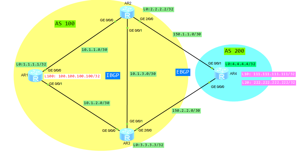
Let’s assume that we have a topology like in below picture:
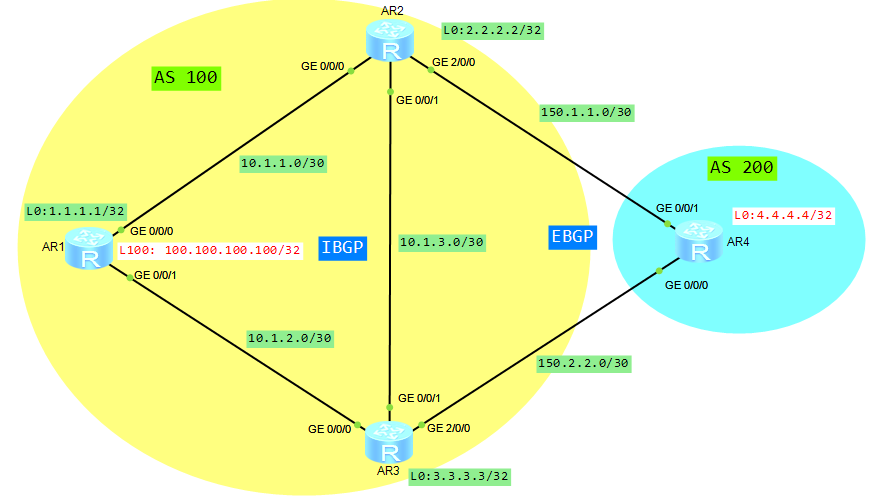
- AR1, AR2 and AR3 are in AS 100.
- AR4 is in AS 200.
- Loopback 100 of router AR1 and loopback 0 of router AR4 are advertised by BGP.
What we want to do is to configure default local preference attribute, which will determine the optimal route, for traffic that leaves AS 100. In our case, the whole traffic leaving AS 100 will go through AR3.
If a BGP device obtains multiple routes from different IBGP peers and these routes have different next hops to the same destination, the BGP device will select the route with the greatest Local_Pref value.
If you want to recall how to configure BGP, just go to “basic BGP in Huawei CLI“.
Check IP routing and BGP routing tables of router AR1:
[AR1]dis ip rout
Route Flags: R - relay, D - download to fib
------------------------------------------------------------------------------
Routing Tables: Public
         Destinations : 18       Routes : 18

Destination/Mask    Proto   Pre  Cost      Flags NextHop         Interface

        1.1.1.1/32  Direct  0    0           D   127.0.0.1       LoopBack0
        2.2.2.2/32  OSPF    10   1           D   10.1.1.2        GigabitEthernet0/0/0
        3.3.3.3/32  OSPF    10   2           D   10.1.1.2        GigabitEthernet0/0/0
        4.4.4.4/32  IBGP    255  0          RD   150.1.1.2       GigabitEthernet0/0/0
       10.1.1.0/30  Direct  0    0           D   10.1.1.1        GigabitEthernet0/0/0
       10.1.1.1/32  Direct  0    0           D   127.0.0.1       GigabitEthernet0/0/0
       10.1.1.3/32  Direct  0    0           D   127.0.0.1       GigabitEthernet0/0/0
       10.1.2.0/30  Direct  0    0           D   10.1.2.1        GigabitEthernet0/0/1
       10.1.2.1/32  Direct  0    0           D   127.0.0.1       GigabitEthernet0/0/1
       10.1.2.3/32  Direct  0    0           D   127.0.0.1       GigabitEthernet0/0/1
       10.1.3.0/30  OSPF    10   2           D   10.1.1.2        GigabitEthernet0/0/0
100.100.100.100/32  Direct  0    0           D   127.0.0.1       LoopBack100
      127.0.0.0/8   Direct  0    0           D   127.0.0.1       InLoopBack0
      127.0.0.1/32  Direct  0    0           D   127.0.0.1       InLoopBack0
127.255.255.255/32  Direct  0    0           D   127.0.0.1       InLoopBack0
      150.1.1.0/30  OSPF    10   2           D   10.1.1.2        GigabitEthernet0/0/0
      150.2.2.0/30  OSPF    10   3           D   10.1.1.2        GigabitEthernet0/0/0
255.255.255.255/32  Direct  0    0           D   127.0.0.1       InLoopBack0

[AR1]dis bgp routing-table

 BGP Local router ID is 1.1.1.1
 Status codes: * - valid, > - best, d - damped,
               h - history,  i - internal, s - suppressed, S - Stale
               Origin : i - IGP, e - EGP, ? - incomplete

 Total Number of Routes: 5
      Network            NextHop        MED        LocPrf    PrefVal Path/Ogn

 *>i  4.4.4.4/32         150.1.1.2       0          100        0      200?
 * i                     150.2.2.2       0          100        0      200?
 *>   100.100.100.100/32 0.0.0.0         0                     0      i
 *>i  150.1.1.0/30       2.2.2.2         0          100        0      i
 *>i  150.2.2.0/30       3.3.3.3         0          100        0      i
As you can see in the IP routing table, Loopback0 of router AR4 is available through IBGP, with the next hop 10.1.1.2 (AR2). From BGP routing table you can notice that there are 2 paths to network 4.4.4.4/32. One of them is chosen as the best path by BGP.
Let’s focus on Local Preference attribute. In our case, we can see that both paths have the same local preference value. Now we will change it to let BGP to choose the best path, based on local preference attribute:
[AR2]bgp 100
[AR2-bgp]default local-preference 200

[AR3]bgp 100
[AR3-bgp]default local-preference 300
Let’s check IP and BGP routing tables of AR1 once again:
[AR1]dis ip rout
Route Flags: R - relay, D - download to fib
------------------------------------------------------------------------------
Routing Tables: Public
         Destinations : 18       Routes : 19

Destination/Mask    Proto   Pre  Cost      Flags NextHop         Interface

        1.1.1.1/32  Direct  0    0           D   127.0.0.1       LoopBack0
        2.2.2.2/32  OSPF    10   1           D   10.1.1.2        GigabitEthernet0/0/0
        3.3.3.3/32  OSPF    10   1           D   10.1.2.2        GigabitEthernet0/0/1
        4.4.4.4/32  IBGP    255  0          RD   150.2.2.2       GigabitEthernet0/0/1
       10.1.1.0/30  Direct  0    0           D   10.1.1.1        GigabitEthernet0/0/0
       10.1.1.1/32  Direct  0    0           D   127.0.0.1       GigabitEthernet0/0/0
       10.1.1.3/32  Direct  0    0           D   127.0.0.1       GigabitEthernet0/0/0
       10.1.2.0/30  Direct  0    0           D   10.1.2.1        GigabitEthernet0/0/1
       10.1.2.1/32  Direct  0    0           D   127.0.0.1       GigabitEthernet0/0/1
       10.1.2.3/32  Direct  0    0           D   127.0.0.1       GigabitEthernet0/0/1
       10.1.3.0/30  OSPF    10   2           D   10.1.1.2        GigabitEthernet0/0/0
                    OSPF    10   2           D   10.1.2.2        GigabitEthernet0/0/1
100.100.100.100/32  Direct  0    0           D   127.0.0.1       LoopBack100
      127.0.0.0/8   Direct  0    0           D   127.0.0.1       InLoopBack0
      127.0.0.1/32  Direct  0    0           D   127.0.0.1       InLoopBack0
127.255.255.255/32  Direct  0    0           D   127.0.0.1       InLoopBack0
      150.1.1.0/30  OSPF    10   2           D   10.1.1.2        GigabitEthernet0/0/0
      150.2.2.0/30  OSPF    10   2           D   10.1.2.2        GigabitEthernet0/0/1
255.255.255.255/32  Direct  0    0           D   127.0.0.1       InLoopBack0

[AR1]dis bgp rout

 BGP Local router ID is 1.1.1.1
 Status codes: * - valid, > - best, d - damped,
               h - history,  i - internal, s - suppressed, S - Stale
               Origin : i - IGP, e - EGP, ? - incomplete

 Total Number of Routes: 4
      Network            NextHop        MED        LocPrf    PrefVal Path/Ogn

 *>i  4.4.4.4/32         150.2.2.2       0          300        0      200?
 *>   100.100.100.100/32 0.0.0.0         0                     0      i
 *>i  150.1.1.0/30       150.2.2.2       0          300        0      200?
 *>i  150.2.2.0/30       3.3.3.3         0          300        0      i
We can use tracert command to check how traffic is going:
[AR1]tracert -a 100.100.100.100 4.4.4.4
 traceroute to  4.4.4.4(4.4.4.4), max hops: 30 ,packet length: 40,press CTRL_C to break
 1 10.1.2.2 110 ms  50 ms  50 ms
 2 150.2.2.2 190 ms  150 ms  120 ms
It means that AR3 router is a gateway for the whole outgoing traffic leaving AS 100.
Let’s check IP routing table of router AR4:
[AR4]dis ip rout
Route Flags: R - relay, D - download to fib
------------------------------------------------------------------------------
Routing Tables: Public
         Destinations : 12       Routes : 12

Destination/Mask    Proto   Pre  Cost      Flags NextHop         Interface

        4.4.4.4/32  Direct  0    0           D   127.0.0.1       LoopBack0
100.100.100.100/32  EBGP    255  0           D   150.1.1.1       GigabitEthernet0/0/1
      127.0.0.0/8   Direct  0    0           D   127.0.0.1       InLoopBack0
      127.0.0.1/32  Direct  0    0           D   127.0.0.1       InLoopBack0
127.255.255.255/32  Direct  0    0           D   127.0.0.1       InLoopBack0
      150.1.1.0/30  Direct  0    0           D   150.1.1.2       GigabitEthernet0/0/1
      150.1.1.2/32  Direct  0    0           D   127.0.0.1       GigabitEthernet0/0/1
      150.1.1.3/32  Direct  0    0           D   127.0.0.1       GigabitEthernet0/0/1
      150.2.2.0/30  Direct  0    0           D   150.2.2.2       GigabitEthernet0/0/0
      150.2.2.2/32  Direct  0    0           D   127.0.0.1       GigabitEthernet0/0/0
      150.2.2.3/32  Direct  0    0           D   127.0.0.1       GigabitEthernet0/0/0
255.255.255.255/32  Direct  0    0           D   127.0.0.1       InLoopBack0
As you can see the whole incoming traffic from AS 200 is going through AR2. So we have proved that BGP local preference attribute is applicable only for traffic leaving AS.
Read More »