How to filter advertised and received routes on Huawei router?
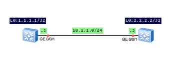
Let’s try to check it based on the following topology:
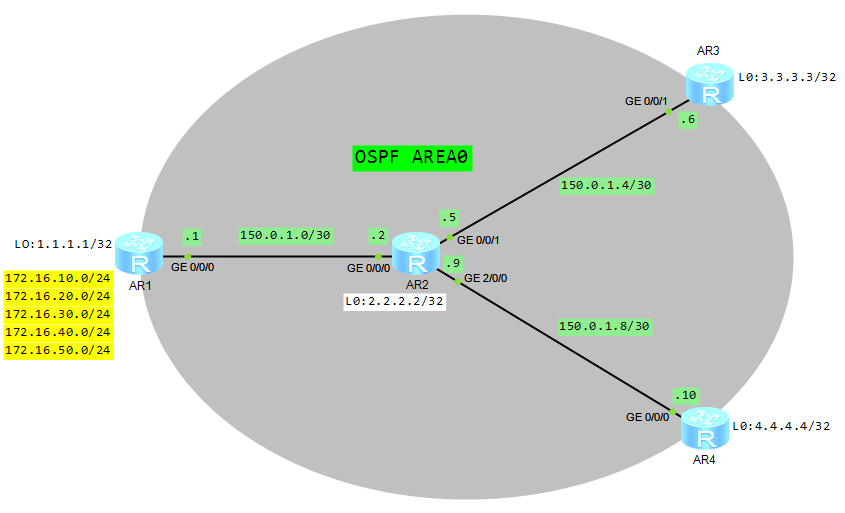
- Configure basic OSPF functions on all routers.
- Configure static routes on AR1 router and import them to OSPF.
- Use filter-policy for advertised routes on AR1.
- Use filter-policy for received routes on AR3.
OSPF configuration (AR2 as an example):
[AR2]dis cur config ospf
#
ospf 1
 area 0.0.0.0
  network 2.2.2.2 0.0.0.0
  network 150.0.1.0 0.0.0.3
  network 150.0.1.4 0.0.0.3
  network 150.0.1.8 0.0.0.3
Configure static routes on AR1:
[AR1]ip route-static 172.16.10.0 255.255.255.0 NULL0
[AR1]ip route-static 172.16.20.0 255.255.255.0 NULL0
[AR1]ip route-static 172.16.30.0 255.255.255.0 NULL0
[AR1]ip route-static 172.16.40.0 255.255.255.0 NULL0
[AR1]ip route-static 172.16.50.0 255.255.255.0 NULL0
Import these routes to OSPF:
[AR1]ospf
[AR1-ospf-1]import-route static
Check IP routing tables of AR2, AR3 and AR4 routers:
[AR2]dis ip routing-table
Route Flags: R - relay, D - download to fib
------------------------------------------------------------------------------
Routing Tables: Public
         Destinations : 22       Routes : 22

Destination/Mask    Proto   Pre  Cost      Flags NextHop         Interface

        1.1.1.1/32  OSPF    10   1           D   150.0.1.1       GigabitEthernet0/0/0
        2.2.2.2/32  Direct  0    0           D   127.0.0.1       LoopBack0
        3.3.3.3/32  OSPF    10   1           D   150.0.1.6       GigabitEthernet0/0/1
        4.4.4.4/32  OSPF    10   1           D   150.0.1.10      GigabitEthernet2/0/0
      127.0.0.0/8   Direct  0    0           D   127.0.0.1       InLoopBack0
      127.0.0.1/32  Direct  0    0           D   127.0.0.1       InLoopBack0
127.255.255.255/32  Direct  0    0           D   127.0.0.1       InLoopBack0
      150.0.1.0/30  Direct  0    0           D   150.0.1.2       GigabitEthernet0/0/0
      150.0.1.2/32  Direct  0    0           D   127.0.0.1       GigabitEthernet0/0/0
      150.0.1.3/32  Direct  0    0           D   127.0.0.1       GigabitEthernet0/0/0
      150.0.1.4/30  Direct  0    0           D   150.0.1.5       GigabitEthernet0/0/1
      150.0.1.5/32  Direct  0    0           D   127.0.0.1       GigabitEthernet0/0/1
      150.0.1.7/32  Direct  0    0           D   127.0.0.1       GigabitEthernet0/0/1
      150.0.1.8/30  Direct  0    0           D   150.0.1.9       GigabitEthernet2/0/0
      150.0.1.9/32  Direct  0    0           D   127.0.0.1       GigabitEthernet2/0/0
     150.0.1.11/32  Direct  0    0           D   127.0.0.1       GigabitEthernet2/0/0
    172.16.10.0/24  O_ASE   150  1           D   150.0.1.1       GigabitEthernet0/0/0
    172.16.20.0/24  O_ASE   150  1           D   150.0.1.1       GigabitEthernet0/0/0
    172.16.30.0/24  O_ASE   150  1           D   150.0.1.1       GigabitEthernet0/0/0
    172.16.40.0/24  O_ASE   150  1           D   150.0.1.1       GigabitEthernet0/0/0
    172.16.50.0/24  O_ASE   150  1           D   150.0.1.1       GigabitEthernet0/0/0
255.255.255.255/32  Direct  0    0           D   127.0.0.1       InLoopBack0

[AR3]dis ip routing-table
Route Flags: R - relay, D - download to fib
------------------------------------------------------------------------------
Routing Tables: Public
         Destinations : 18       Routes : 18

Destination/Mask    Proto   Pre  Cost      Flags NextHop         Interface

        1.1.1.1/32  OSPF    10   2           D   150.0.1.5       GigabitEthernet0/0/1
        2.2.2.2/32  OSPF    10   1           D   150.0.1.5       GigabitEthernet0/0/1
        3.3.3.3/32  Direct  0    0           D   127.0.0.1       LoopBack0
        4.4.4.4/32  OSPF    10   2           D   150.0.1.5       GigabitEthernet0/0/1
      127.0.0.0/8   Direct  0    0           D   127.0.0.1       InLoopBack0
      127.0.0.1/32  Direct  0    0           D   127.0.0.1       InLoopBack0
127.255.255.255/32  Direct  0    0           D   127.0.0.1       InLoopBack0
      150.0.1.0/30  OSPF    10   2           D   150.0.1.5       GigabitEthernet0/0/1
      150.0.1.4/30  Direct  0    0           D   150.0.1.6       GigabitEthernet0/0/1
      150.0.1.6/32  Direct  0    0           D   127.0.0.1       GigabitEthernet0/0/1
      150.0.1.7/32  Direct  0    0           D   127.0.0.1       GigabitEthernet0/0/1
      150.0.1.8/30  OSPF    10   2           D   150.0.1.5       GigabitEthernet0/0/1
    172.16.10.0/24  O_ASE   150  1           D   150.0.1.5       GigabitEthernet0/0/1
    172.16.20.0/24  O_ASE   150  1           D   150.0.1.5       GigabitEthernet0/0/1
    172.16.30.0/24  O_ASE   150  1           D   150.0.1.5       GigabitEthernet0/0/1
    172.16.40.0/24  O_ASE   150  1           D   150.0.1.5       GigabitEthernet0/0/1
    172.16.50.0/24  O_ASE   150  1           D   150.0.1.5       GigabitEthernet0/0/1
255.255.255.255/32  Direct  0    0           D   127.0.0.1       InLoopBack0

[AR4]dis ip routing-table
Route Flags: R - relay, D - download to fib
------------------------------------------------------------------------------
Routing Tables: Public
         Destinations : 18       Routes : 18

Destination/Mask    Proto   Pre  Cost      Flags NextHop         Interface

        1.1.1.1/32  OSPF    10   2           D   150.0.1.9       GigabitEthernet0/0/0
        2.2.2.2/32  OSPF    10   1           D   150.0.1.9       GigabitEthernet0/0/0
        3.3.3.3/32  OSPF    10   2           D   150.0.1.9       GigabitEthernet0/0/0
        4.4.4.4/32  Direct  0    0           D   127.0.0.1       LoopBack0
      127.0.0.0/8   Direct  0    0           D   127.0.0.1       InLoopBack0
      127.0.0.1/32  Direct  0    0           D   127.0.0.1       InLoopBack0
127.255.255.255/32  Direct  0    0           D   127.0.0.1       InLoopBack0
      150.0.1.0/30  OSPF    10   2           D   150.0.1.9       GigabitEthernet0/0/0
      150.0.1.4/30  OSPF    10   2           D   150.0.1.9       GigabitEthernet0/0/0
      150.0.1.8/30  Direct  0    0           D   150.0.1.10      GigabitEthernet0/0/0
     150.0.1.10/32  Direct  0    0           D   127.0.0.1       GigabitEthernet0/0/0
     150.0.1.11/32  Direct  0    0           D   127.0.0.1       GigabitEthernet0/0/0
    172.16.10.0/24  O_ASE   150  1           D   150.0.1.9       GigabitEthernet0/0/0
    172.16.20.0/24  O_ASE   150  1           D   150.0.1.9       GigabitEthernet0/0/0
    172.16.30.0/24  O_ASE   150  1           D   150.0.1.9       GigabitEthernet0/0/0
    172.16.40.0/24  O_ASE   150  1           D   150.0.1.9       GigabitEthernet0/0/0
    172.16.50.0/24  O_ASE   150  1           D   150.0.1.9       GigabitEthernet0/0/0
255.255.255.255/32  Direct  0    0           D   127.0.0.1       InLoopBack0
As you can see, all static routes imported to OSPF are available as O_ASE.
Now we can filter routes advertised by AR1 router. Only three routes will be advertised: 172.16.10.0/24, 172.16.20.0/24 and 172.16.30.0/24.
Create IP prefix list named AR1toAR2 and permit these 3 routes:
[AR1]ip ip-prefix AR1toAR2 index 10 permit 172.16.10.0 24
[AR1]ip ip-prefix AR1toAR2 index 20 permit 172.16.20.0 24
[AR1]ip ip-prefix AR1toAR2 index 30 permit 172.16.30.0 24
Apply filter-policy to OSPF:
[AR1]ospf
[AR1-ospf-1]filter-policy ip-prefix AR1toAR2 export
Check IP routing table, for instance AR2:
[AR2]dis ip routing-table
Route Flags: R - relay, D - download to fib
------------------------------------------------------------------------------
Routing Tables: Public
         Destinations : 20       Routes : 20

Destination/Mask    Proto   Pre  Cost      Flags NextHop         Interface

        1.1.1.1/32  OSPF    10   1           D   150.0.1.1       GigabitEthernet0/0/0
        2.2.2.2/32  Direct  0    0           D   127.0.0.1       LoopBack0
        3.3.3.3/32  OSPF    10   1           D   150.0.1.6       GigabitEthernet0/0/1
        4.4.4.4/32  OSPF    10   1           D   150.0.1.10      GigabitEthernet2/0/0
      127.0.0.0/8   Direct  0    0           D   127.0.0.1       InLoopBack0
      127.0.0.1/32  Direct  0    0           D   127.0.0.1       InLoopBack0
127.255.255.255/32  Direct  0    0           D   127.0.0.1       InLoopBack0
      150.0.1.0/30  Direct  0    0           D   150.0.1.2       GigabitEthernet0/0/0
      150.0.1.2/32  Direct  0    0           D   127.0.0.1       GigabitEthernet0/0/0
      150.0.1.3/32  Direct  0    0           D   127.0.0.1       GigabitEthernet0/0/0
      150.0.1.4/30  Direct  0    0           D   150.0.1.5       GigabitEthernet0/0/1
      150.0.1.5/32  Direct  0    0           D   127.0.0.1       GigabitEthernet0/0/1
      150.0.1.7/32  Direct  0    0           D   127.0.0.1       GigabitEthernet0/0/1
      150.0.1.8/30  Direct  0    0           D   150.0.1.9       GigabitEthernet2/0/0
      150.0.1.9/32  Direct  0    0           D   127.0.0.1       GigabitEthernet2/0/0
     150.0.1.11/32  Direct  0    0           D   127.0.0.1       GigabitEthernet2/0/0
    172.16.10.0/24  O_ASE   150  1           D   150.0.1.1       GigabitEthernet0/0/0
    172.16.20.0/24  O_ASE   150  1           D   150.0.1.1       GigabitEthernet0/0/0
    172.16.30.0/24  O_ASE   150  1           D   150.0.1.1       GigabitEthernet0/0/0
255.255.255.255/32  Direct  0    0           D   127.0.0.1       InLoopBack0
From the output you can noticed that only three routes are advertised by AR1.
Now configure filter-policy for routes received by AR3.
Create IP prefix list on AR3 that permits only 172.16.10.0/24 route:
[AR3]ip ip-prefix AR2toAR3 index 10 permit 172.16.10.0 24
Apply filter-policy to OSPF as import:
[AR3]ospf
[AR3-ospf-1]filter-policy ip-prefix AR2toAR3 import
Check routing table of AR3 router:
[AR3]dis ip routing-table
Route Flags: R - relay, D - download to fib
------------------------------------------------------------------------------
Routing Tables: Public
         Destinations : 9        Routes : 9

Destination/Mask    Proto   Pre  Cost      Flags NextHop         Interface

        3.3.3.3/32  Direct  0    0           D   127.0.0.1       LoopBack0
      127.0.0.0/8   Direct  0    0           D   127.0.0.1       InLoopBack0
      127.0.0.1/32  Direct  0    0           D   127.0.0.1       InLoopBack0
127.255.255.255/32  Direct  0    0           D   127.0.0.1       InLoopBack0
      150.0.1.4/30  Direct  0    0           D   150.0.1.6       GigabitEthernet0/0/1
      150.0.1.6/32  Direct  0    0           D   127.0.0.1       GigabitEthernet0/0/1
      150.0.1.7/32  Direct  0    0           D   127.0.0.1       GigabitEthernet0/0/1
    172.16.10.0/24  O_ASE   150  1           D   150.0.1.5       GigabitEthernet0/0/1
255.255.255.255/32  Direct  0    0           D   127.0.0.1       InLoopBack0
Check IP routing table of AR4 router:
[AR4]dis ip routing-table
Route Flags: R - relay, D - download to fib
------------------------------------------------------------------------------
Routing Tables: Public
         Destinations : 16       Routes : 16

Destination/Mask    Proto   Pre  Cost      Flags NextHop         Interface

        1.1.1.1/32  OSPF    10   2           D   150.0.1.9       GigabitEthernet0/0/0
        2.2.2.2/32  OSPF    10   1           D   150.0.1.9       GigabitEthernet0/0/0
        3.3.3.3/32  OSPF    10   2           D   150.0.1.9       GigabitEthernet0/0/0
        4.4.4.4/32  Direct  0    0           D   127.0.0.1       LoopBack0
      127.0.0.0/8   Direct  0    0           D   127.0.0.1       InLoopBack0
      127.0.0.1/32  Direct  0    0           D   127.0.0.1       InLoopBack0
127.255.255.255/32  Direct  0    0           D   127.0.0.1       InLoopBack0
      150.0.1.0/30  OSPF    10   2           D   150.0.1.9       GigabitEthernet0/0/0
      150.0.1.4/30  OSPF    10   2           D   150.0.1.9       GigabitEthernet0/0/0
      150.0.1.8/30  Direct  0    0           D   150.0.1.10      GigabitEthernet0/0/0
     150.0.1.10/32  Direct  0    0           D   127.0.0.1       GigabitEthernet0/0/0
     150.0.1.11/32  Direct  0    0           D   127.0.0.1       GigabitEthernet0/0/0
    172.16.10.0/24  O_ASE   150  1           D   150.0.1.9       GigabitEthernet0/0/0
    172.16.20.0/24  O_ASE   150  1           D   150.0.1.9       GigabitEthernet0/0/0
    172.16.30.0/24  O_ASE   150  1           D   150.0.1.9       GigabitEthernet0/0/0
255.255.255.255/32  Direct  0    0           D   127.0.0.1       InLoopBack0
As you can see only one route is received by AR3. So filter-policy works correctly. AR4 router still receives all three routes.
Read More »