Some time ago I published article about BGP local preference attribute. Today I’d like to show you how to configure BGP MED attribute.
What is it for?
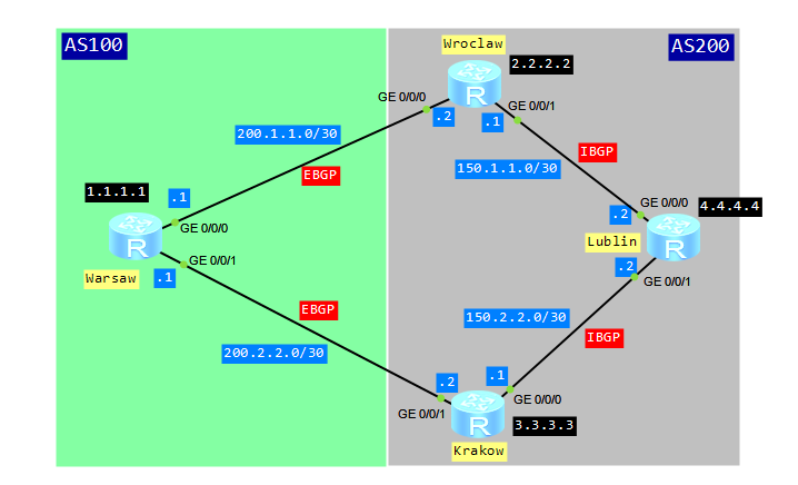
The multi-exit discriminator MED determines an optimal route for incoming traffic of an AS. When a BGP device obtains multiple routes to the same destination but with different next hops from EBGP peers, the BGP device selects the route with the smallest MED value as the optimal route. Simply saying, configuring MED attribute, we would like to show the next hop for traffic coming from EBGP peer. The MED attribute is exchanged only between two neighboring ASs. The AS that receives the MED attribute does not advertise it to any other ASs.
Let’s look at typical scenario for MED attribute configuration:
If you want to recall the BGP configuration, just go to “basic BGP in Huawei CLI” article.
What we want to do in this lab is to force Warsaw router to send traffic to network 4.4.4.4 through Krakow router. Of course we will use BGP MED attribute to achieve this.
Configure IGP for AS200:
[Wroclaw]dis cur config ospf
#
ospf 1
 area 0.0.0.0
  network 2.2.2.2 0.0.0.0
  network 150.1.1.0 0.0.0.3

[Krakow]dis cur config ospf
#
ospf 1
 area 0.0.0.0
  network 3.3.3.3 0.0.0.0
  network 150.2.2.0 0.0.0.3

[Lublin]dis cur config ospf
#
ospf 1
 area 0.0.0.0
  network 4.4.4.4 0.0.0.0
  network 150.1.1.0 0.0.0.3
  network 150.2.2.0 0.0.0.3
Configure IBGP and BGP:
[Warsaw]dis cur config bgp
#
bgp 100
 router-id 1.1.1.1
 peer 200.1.1.2 as-number 200
 peer 200.2.2.2 as-number 200
 #
 ipv4-family unicast
  undo synchronization
  network 1.1.1.1 255.255.255.255
  peer 200.1.1.2 enable
  peer 200.2.2.2 enable

[Wroclaw]dis cu config bgp
#
bgp 200
 router-id 2.2.2.2
 peer 3.3.3.3 as-number 200
 peer 3.3.3.3 connect-interface LoopBack0
 peer 4.4.4.4 as-number 200
 peer 4.4.4.4 connect-interface LoopBack0
 peer 200.1.1.1 as-number 100
 #
 ipv4-family unicast
  undo synchronization
  peer 3.3.3.3 enable
  peer 3.3.3.3 next-hop-local
  peer 4.4.4.4 enable
  peer 4.4.4.4 next-hop-local
  peer 200.1.1.1 enable

[Krakow]dis cur config bgp
#
bgp 200
 peer 2.2.2.2 as-number 200
 peer 2.2.2.2 connect-interface LoopBack0
 peer 4.4.4.4 as-number 200
 peer 4.4.4.4 connect-interface LoopBack0
 peer 200.2.2.1 as-number 100
 #
 ipv4-family unicast
  undo synchronization
  peer 2.2.2.2 enable
  peer 2.2.2.2 next-hop-local
  peer 4.4.4.4 enable
  peer 4.4.4.4 next-hop-local
  peer 200.2.2.1 enable

[Lublin]dis cur config bgp
#
bgp 200
 peer 2.2.2.2 as-number 200
 peer 2.2.2.2 connect-interface LoopBack0
 peer 3.3.3.3 as-number 200
 peer 3.3.3.3 connect-interface LoopBack0
 #
 ipv4-family unicast
  undo synchronization
  peer 2.2.2.2 enable
  peer 3.3.3.3 enable
Configure Loopback100 on Lublin router and add its address 100.100.100.100/32 to BGP:
[Lublin]interface LoopBack 100
[Lublin-LoopBack100]ip add 100.100.100.100 32

[Lublin-bgp]ipv4-family unicast
[Lublin-bgp-af-ipv4]network 100.100.100.100 255.255.255.255
View BGP routing table of Warsaw router:
<Warsaw>dis bgp routing-table

 BGP Local router ID is 1.1.1.1
 Status codes: * - valid, > - best, d - damped,
               h - history,  i - internal, s - suppressed, S - Stale
               Origin : i - IGP, e - EGP, ? - incomplete

 Total Number of Routes: 3
      Network            NextHop        MED        LocPrf    PrefVal Path/Ogn

 *>   1.1.1.1/32         0.0.0.0         0                     0      i
 *>   100.100.100.100/32 200.1.1.2                             0      200i
 *                       200.2.2.2                             0      200i

<Warsaw>dis bgp routing-table 100.100.100.100

 BGP local router ID : 1.1.1.1
 Local AS number : 100
 Paths:   2 available, 1 best, 1 select
 BGP routing table entry information of 100.100.100.100/32:
 From: 200.1.1.2 (2.2.2.2)
 Route Duration: 00h00m29s
 Direct Out-interface: GigabitEthernet0/0/0
 Original nexthop: 200.1.1.2
 Qos information : 0x0
 AS-path 200, origin igp, pref-val 0, valid, external, best, select, active, pre
255
 Advertised to such 2 peers:
    200.1.1.2
    200.2.2.2
 BGP routing table entry information of 100.100.100.100/32:
 From: 200.2.2.2 (3.3.3.3)
 Route Duration: 01h21m00s
 Direct Out-interface: GigabitEthernet0/0/1
 Original nexthop: 200.2.2.2
 Qos information : 0x0
 AS-path 200, origin igp, pref-val 0, valid, external, pre 255, not preferred for
 router ID
 Not advertised to any peer yet
As you can see from the output, there are 2 valid routes to 100.100.100.100. The route with the next hop 200.1.1.2 is the optimal route, because of a smaller router ID. A default value of MED is 0.
Now we can set MED attribute for routes advertised by Wroclaw router to Warsaw:
[Wroclaw]route-policy med permit node 10
Info: New Sequence of this List.
[Wroclaw-route-policy] apply cost 200

[Wroclaw]bgp 200
[Wroclaw-bgp]ipv4-family unicast
[Wroclaw-bgp-af-ipv4]peer 200.1.1.1 route-policy med export
Look at BGP routing table of Warsaw router once again:
[Warsaw]dis bgp routing-table

 BGP Local router ID is 1.1.1.1
 Status codes: * - valid, > - best, d - damped,
               h - history,  i - internal, s - suppressed, S - Stale
               Origin : i - IGP, e - EGP, ? - incomplete

 Total Number of Routes: 3
      Network            NextHop        MED        LocPrf    PrefVal Path/Ogn

 *>   1.1.1.1/32         0.0.0.0         0                     0      i
 *>   100.100.100.100/32 200.2.2.2                             0      200i
 *                       200.1.1.2       200                   0      200i

[Warsaw]dis bgp routing-table 100.100.100.100

BGP local router ID : 1.1.1.1
Local AS number : 100
Paths: 2 available, 1 best, 1 select
BGP routing table entry information of 100.100.100.100/32:
From: 200.2.2.2 (3.3.3.3)
Route Duration: 01h30m40s
Direct Out-interface: GigabitEthernet0/0/1
Original nexthop: 200.2.2.2
Qos information : 0x0
AS-path 200, origin igp, pref-val 0, valid, external, best, select, active, pre
255
Advertised to such 2 peers:
200.1.1.2
200.2.2.2
BGP routing table entry information of 100.100.100.100/32:
From: 200.1.1.2 (2.2.2.2)
Route Duration: 00h00m29s
Direct Out-interface: GigabitEthernet0/0/0
Original nexthop: 200.1.1.2
Qos information : 0x0
AS-path 200, origin igp, MED 200, pref-val 0, valid, external, pre 255, not pref
erred for MED
Not advertised to any peer yet
As you can see, the router with the next hop 200.2.2.2 is the optimal route to 100.100.100.100. It was chosen because of MED attribute (smaller MED = best route).
To be sure just use tracert command on Warsaw router:
<Warsaw>tracert -a 1.1.1.1 100.100.100.100

traceroute to 100.100.100.100(100.100.100.100), max hops: 30 ,packet length: 40,press CTRL_C to break

1 200.2.2.2 60 ms 50 ms 30 ms

2 150.2.2.2 80 ms 60 ms 60 ms
Anyway, traffic from Lublin router to Warsaw still goes through Wroclaw router:
<Lublin>tracert -a 100.100.100.100 1.1.1.1

traceroute to 1.1.1.1(1.1.1.1), max hops: 30 ,packet length: 40,press CTRL_C to break

1 150.1.1.1 50 ms 50 ms 40 ms

2 200.1.1.1 70 ms 60 ms 40 ms
At the end I have a question for you. Is it possible to compare MED attributes of routes, received from different EBGP peers? If yes, how to do this? Waiting for your comments.