In traditional 802.1Q protocol, service provider should assign different VLAN IDs to users of different VLANs. The numer of VLANs is limited to 4094 IDs. In addition, different users cannot use the same VLAN ID.
A simple method to solve this is to implement QinQ. The QinQ technology improves the utilization of VLANs by adding another 802.1Q tag to a packet with an 802.1Q tag. In this manner, services from the private VLAN can be transparently transmitted through the public network. The ISP network only provides one VLAN ID for different VLANs from the same user network. This saves VLAN IDs of an ISP. Meanwhile, the QinQ provides a simple Layer 2 VPN solution to a small MAN or a local area networks.
QinQ tunneling on Huawei switches
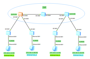
Let’s assume that we have two enteprise networks. Each enterprise has two branch offices, located in different cities. As an ISP, we cannot force these enterprises to use different VLAN planning. In our case, both use VLAN 10 and our task is to transparently transmitt traffic, through ISP network, between remote offices.
What we want to achieve is to ensure communication between remote offices of each enterprise and to block communication between Enterprise_1 and Enterprise_2. We can use basic QinQ tunneling in this case. It adds the same outer VLAN tag to all the frames entering a Layer 2 port.
QinQ topology
QinQ configuration on Huawei switches
1. Configure enteprise switches to allow VLAN 10 to be transmitted. All enterprise switches in our case have the same configuration. You can recall VLAN configuration looking at the following post VLAN, trunk, VLANIF (SVI) on Huawei switch.
vlan batch 10
#
interface Ethernet0/0/1
 port link-type access
 port default vlan 10
#
interface GigabitEthernet0/0/1
 port link-type trunk
 port trunk allow-pass vlan 10
2. Create VLANs 100 and 200 on all ISP switches. Below SwitchA as an example.
[SwitchA]vlan batch 100 200
3. Allow VLANs 100 and 200 to be transmitted between ISP switches.
[SwitchA]interface GigabitEthernet 0/0/2
[SwitchA-GigabitEthernet0/0/2]port link-type trunk
[SwitchA-GigabitEthernet0/0/2]port trunk allow-pass vlan 100 200

[SwitchB]interface GigabitEthernet 0/0/4
[SwitchB-GigabitEthernet0/0/4]port link-type trunk
[SwitchB-GigabitEthernet0/0/4]port trunk allow-pass vlan 100 200

[ISP]interface GigabitEthernet 0/0/2
[ISP-GigabitEthernet0/0/2]port link-type trunk
[ISP-GigabitEthernet0/0/2]port trunk allow-pass vlan 100 200

[ISP]interface GigabitEthernet 0/0/4
[ISP-GigabitEthernet0/0/4]port link-type trunk
[ISP-GigabitEthernet0/0/4]port trunk allow-pass vlan 100 200
4. Set interfaces of SwitchA and SwitchB towards Enteprise_1 and Enterprise_2 as QinQ with VLAN tag 100 and 200 accordingly.
[SwitchA]interface GigabitEthernet 0/0/1
 [SwitchA-GigabitEthernet0/0/1] port link-type dot1q-tunnel
 [SwitchA-GigabitEthernet0/0/1] port default vlan 100

[SwitchA]interface GigabitEthernet 0/0/3
 [SwitchA-GigabitEthernet0/0/3] port link-type dot1q-tunnel
 [SwitchA-GigabitEthernet0/0/3] port default vlan 200

[SwitchB]interface GigabitEthernet 0/0/1
 [SwitchB-GigabitEthernet0/0/1] port link-type dot1q-tunnel
 [SwitchB-GigabitEthernet0/0/1] port default vlan 100

[SwitchB]interface GigabitEthernet 0/0/3
 [SwitchB-GigabitEthernet0/0/3] port link-type dot1q-tunnel
 [SwitchB-GigabitEthernet0/0/3] port default vlan 200
5. Check communication between branch offices in Enterprise_1 and in Enterprise_2.
PC_Enterprise_1>ping 172.16.1.2

Ping 172.16.1.2: 32 data bytes, Press Ctrl_C to break
From 172.16.1.2: bytes=32 seq=1 ttl=128 time=140 ms
From 172.16.1.2: bytes=32 seq=2 ttl=128 time=94 ms
From 172.16.1.2: bytes=32 seq=3 ttl=128 time=109 ms
From 172.16.1.2: bytes=32 seq=4 ttl=128 time=125 ms
From 172.16.1.2: bytes=32 seq=5 ttl=128 time=125 ms
PC_Enterprise_2>ping 172.16.1.11

Ping 172.16.1.11: 32 data bytes, Press Ctrl_C to break
From 172.16.1.11: bytes=32 seq=1 ttl=128 time=156 ms
From 172.16.1.11: bytes=32 seq=2 ttl=128 time=94 ms
From 172.16.1.11: bytes=32 seq=3 ttl=128 time=125 ms
From 172.16.1.11: bytes=32 seq=4 ttl=128 time=109 ms
From 172.16.1.11: bytes=32 seq=5 ttl=128 time=125 ms
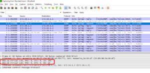
Let’s look into the ICMP packet:
As you can see there are 2 VLAN tags inside ISP network so QinQ is working correctly.
6. Notice that communication between Enterprise_1 and Enterprise_2 is blocked.
PC_Enterprise_1>ping 172.16.1.11

Ping 172.16.1.11: 32 data bytes, Press Ctrl_C to break
From 172.16.1.1: Destination host unreachable
From 172.16.1.1: Destination host unreachable
From 172.16.1.1: Destination host unreachable
From 172.16.1.1: Destination host unreachable
From 172.16.1.1: Destination host unreachable
 Labnario Huawei From Scratch


Olá! Boa noite! Sou do Brasil e gostaria de agradecer pelo post. Me ajudou muito. Muito obrigado por tudo.
Oi fico feliz em te ajudar.
Great post, do you need to change the mtu along the path?
where from the vlan 100 and 200