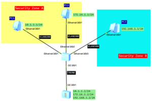
It’s time to check a firewall available in eNSP simulator. Today a simple task, just configuring inter-VLAN communication on Huawei USG5500.
Let’s look at the following topology:
Configuration roadmap:
- Configure L2 communication on the switch.
- As the switch is L2, configure subinterfaces on the firewall and enable L3 communication between different VLANs.
- Set IP addresses and gateways for all PCs.
- Create 2 security zones and configure interzone packet-filterfing to control traffic between VLANs.
- Security requirements for the network:
- PC1 in VLAN100 and PC2 in VLAN200 can communicate each other.
- PC3 in VLAN300 can access PC1 and PC2. PC1 and PC2 cannot access PC3.
L2 communication on the switch:
#
interface Ethernet0/0/1
 port link-type access
 port default vlan 100
#
interface Ethernet0/0/2
 port link-type access
 port default vlan 200
#
interface Ethernet0/0/3
 port link-type access
 port default vlan 300
#
interface GigabitEthernet0/0/1
 port link-type trunk
 port trunk allow-pass vlan 100 200 300
L3 communication on the firewall:
#
interface GigabitEthernet0/0/1.100
 vlan-type dot1q 100
 alias GigabitEthernet0/0/1.100
 ip address 10.1.1.2 255.255.255.0
#
interface GigabitEthernet0/0/1.200
 vlan-type dot1q 200
 alias GigabitEthernet0/0/1.200
 ip address 172.16.1.2 255.255.255.0
#
interface GigabitEthernet0/0/1.300
 vlan-type dot1q 300
 alias GigabitEthernet0/0/1.300
 ip address 192.168.1.2 255.255.255.0
#
Create two security zones and add subinterfaces to them based on the above requirements:
[Firewall]firewall zone name a
[Firewall-zone-a]set priority 70
[Firewall-zone-a]add interface GigabitEthernet0/0/1.100
[Firewall-zone-a] add interface GigabitEthernet0/0/1.200
[Firewall-zone-a]

[Firewall]firewall zone name b
[Firewall-zone-b]set priority 80
[Firewall-zone-b] add interface GigabitEthernet0/0/1.300
[Firewall-zone-b]
A security zone is a security concept, based on which most security policies are implemented. A security zone is a set of the networks connected by interfaces. Users on these networks have the same security attributes. USG has 4 security zones by default, which cannot be deleted and their security level cannot be changed. You can create security zones and specify their security levels according to actual networking requirements. The security level ranges from 1 to 100. The larger the value, the higher the security level.
Configure interzone packet filtering based on the above requirements:
[Firewall]policy interzone b a inbound
[Firewall-policy-interzone-b-a-inbound]policy 1
[Firewall-policy-interzone-b-a-inbound-1]  action deny
[Firewall-policy-interzone-b-a-inbound-1]  policy source 10.1.1.0 0.0.0.255
[Firewall-policy-interzone-b-a-inbound-1]  policy source 172.16.1.0 0.0.0.255
[Firewall-policy-interzone-b-a-inbound-1]  policy destination 192.168.1.0 0.0.0.255

[Firewall]policy interzone b a outbound
[Firewall-policy-interzone-b-a-outbound]policy 1
[Firewall-policy-interzone-b-a-outbound-1]  action permit
[Firewall-policy-interzone-b-a-outbound-1]  policy source 192.168.1.0 0.0.0.255
A security interzone is to describe the transmission channel of the traffic, which is the unique path between two zones.
Data flows in the interzone are directional:
- Outbound – indicates that data is transmitted from a higher security zone to a lower security zone.
- Inbound – indicates that data is transmitted from a lower security zone to a higher security zone
Verification:
PC1>ping 172.16.1.1

Ping 172.16.1.1: 32 data bytes, Press Ctrl_C to break
From 172.16.1.1: bytes=32 seq=1 ttl=127 time=62 ms
From 172.16.1.1: bytes=32 seq=2 ttl=127 time=78 ms
From 172.16.1.1: bytes=32 seq=3 ttl=127 time=47 ms
From 172.16.1.1: bytes=32 seq=4 ttl=127 time=63 ms
From 172.16.1.1: bytes=32 seq=5 ttl=127 time=62 ms

--- 172.16.1.1 ping statistics ---
  5 packet(s) transmitted
  5 packet(s) received
  0.00% packet loss
  round-trip min/avg/max = 47/62/78 ms

PC1>ping 192.168.1.1

Ping 192.168.1.1: 32 data bytes, Press Ctrl_C to break
Request timeout!
Request timeout!
Request timeout!
Request timeout!
Request timeout!

--- 192.168.1.1 ping statistics ---
  5 packet(s) transmitted
  0 packet(s) received
  100.00% packet loss

PC1>
PC2>ping 10.1.1.1

Ping 10.1.1.1: 32 data bytes, Press Ctrl_C to break
From 10.1.1.1: bytes=32 seq=1 ttl=127 time=63 ms
From 10.1.1.1: bytes=32 seq=2 ttl=127 time=62 ms
From 10.1.1.1: bytes=32 seq=3 ttl=127 time=78 ms
From 10.1.1.1: bytes=32 seq=4 ttl=127 time=63 ms
From 10.1.1.1: bytes=32 seq=5 ttl=127 time=63 ms

--- 10.1.1.1 ping statistics ---
  5 packet(s) transmitted
  5 packet(s) received
  0.00% packet loss
  round-trip min/avg/max = 62/65/78 ms

PC2>ping 192.168.1.1

Ping 192.168.1.1: 32 data bytes, Press Ctrl_C to break
Request timeout!
Request timeout!
Request timeout!
Request timeout!
Request timeout!

--- 192.168.1.1 ping statistics ---
  5 packet(s) transmitted
  0 packet(s) received
  100.00% packet loss

PC2>
PC3>ping 10.1.1.1

Ping 10.1.1.1: 32 data bytes, Press Ctrl_C to break
From 10.1.1.1: bytes=32 seq=1 ttl=127 time=78 ms
From 10.1.1.1: bytes=32 seq=2 ttl=127 time=62 ms
From 10.1.1.1: bytes=32 seq=3 ttl=127 time=46 ms
From 10.1.1.1: bytes=32 seq=4 ttl=127 time=62 ms
From 10.1.1.1: bytes=32 seq=5 ttl=127 time=78 ms

--- 10.1.1.1 ping statistics ---
  5 packet(s) transmitted
  5 packet(s) received
  0.00% packet loss
  round-trip min/avg/max = 46/65/78 ms

PC3>ping 172.16.1.1

Ping 172.16.1.1: 32 data bytes, Press Ctrl_C to break
From 172.16.1.1: bytes=32 seq=1 ttl=127 time=63 ms
From 172.16.1.1: bytes=32 seq=2 ttl=127 time=47 ms
From 172.16.1.1: bytes=32 seq=3 ttl=127 time=63 ms
From 172.16.1.1: bytes=32 seq=4 ttl=127 time=62 ms
From 172.16.1.1: bytes=32 seq=5 ttl=127 time=47 ms

--- 172.16.1.1 ping statistics ---
  5 packet(s) transmitted
  5 packet(s) received
  0.00% packet loss
  round-trip min/avg/max = 47/56/63 ms

PC3>
As you can see from the outputs, PC1 and PC2 can communicate each other but cannot access PC3. PC3 can access PC1 and PC2 which completes our task.
 Labnario Huawei From Scratch
