Spanning Tree protocol is a loop prevention mechanism in a bridged LAN. Every STP topology has its own root bridge, which determines how STP topology is calculated. The role of the root bridge is to act as a reference point in the network, so that all other switches can determine, how far each of their ports is from the root bridge. The port, which has the lowest path cost, is placed into a forwarding state. All other ports, that can lead to the root bridge, are blocked. Ports in the switching topology, which lead away from the Root Bridge, remain forwarding. You can recall STP operations reading the following article: “Multiple Spanning Tree Protocol on Huawei switch“.
How does the root bridge election process work?
The root bridge for each STP instance is determined by the bridge ID. The bridge ID consists of a configurable bridge priority and the MAC address of the bridge:
[Huawei]display stp
-------[CIST Global Info][Mode MSTP]-------
CIST Bridge         :32768.4c1f-ccd4-1c03
In this example the bridge ID is 32768.4c1f-ccd4-1c03, where:
- 32768 is the bridge priority
- 4c1f-ccd4-1c03 is the MAC address of the bridge.
The bridge with the lowest bridge ID is elected as the root bridge. If the bridge priorities are equal, or if the bridge priority is not configured, the bridge with the lowest MAC address is elected the root bridge.
How to change the bridge priority on Huawei switch?
[Huawei]stp priority ?
  INTEGER  Bridge priority, in steps of 4096
A predefined macro can be also used to change bridge priority:
[Huawei]stp root ?
  primary    Primary root switch
  secondary  Secondary root switch
The same macro, when changing bridge priority in particular STP instance:
[Huawei]stp instance 1 root ?
  primary    Primary root switch
  secondary  Secondary root switch
The first option changes priority to 0, the second to 4096. Default bridge priority equals to 32768.
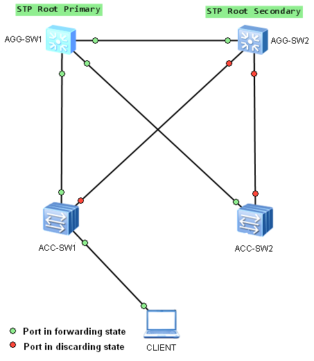
Any switch can be a root bridge in a network. But the most optimal forwarding topology places the root bridge at a specific predetermined location. Let’s take the following example:
Aggregation switch AGG-SW1 was elected as the root bridge and AGG-SW2 as the secondary root bridge, in case of AGG-SW1’s failure. STP topology was built as expected, fast speed links are used to forward traffic between devices.
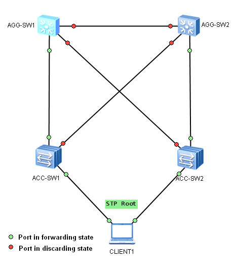
Even if the root bridge was configured with priority 0, every switch in this network, with priority 0 and a lower MAC address, can be elected as a new root bridge. Let’s imagine a situation, where someone connects additional switch, or just a software-based bridge application lunched on a PC with dual NICs and lower bridge ID, like below:
Our PC was elected as a new root bridge for this VLAN. STP topology was changed and now, low-speed access links are used to forward traffic between aggregation switches. If more data flow via the aggregation link in that VLAN, than this link can accommodate, the drop of some frames occur. As a result, network performance can be affected.
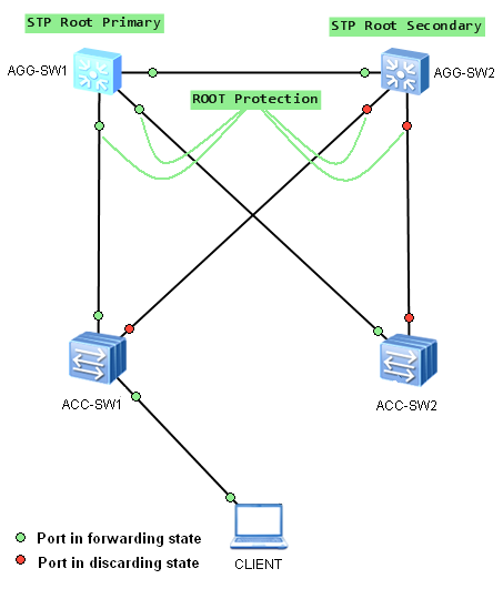
To prevent this from happening, STP Root Protection can be used on interfaces, which should not receive superior BPDUs. These interfaces usually are located on an administrative boundary. In our case, Root Protection feature should be enabled on interfaces as in the picture below:
To enable Root Protection on Huawei switch, use command:
[Huawei]int GigabitEthernet 0/0/1
[Huawei-GigabitEthernet0/0/1]stp root-protection
Remember, that root protection takes effect only on designated ports.
 Labnario Huawei From Scratch


